How to fit Megasquirt to your 4EFTE

speedfreaq

Member +
How to Megasquirt (MS) your 4EFTE

This is an attempt to document how I got my MS to run my 4efte use whatever information you find here at your own risk.

Firstly if you are reading this then you know what MS is…
So you will either have bought one already built or like me buy the kit and build it yourself.

All references made here will be for MS2 extra as that is the code I am using.

So the options for MS are numerous.
DIY autotune (http://www.diyautotune.com/) has one of the most complete resource centers for MS. With lots of different kits to chose from and completely assembled ecu as well.
www.glensgarage.com is another option as well for kits and complete MS assemblies.

The kit I am using is the MS2 V3 board. (bought from DIYautotune)
msx30-c_fr.jpg


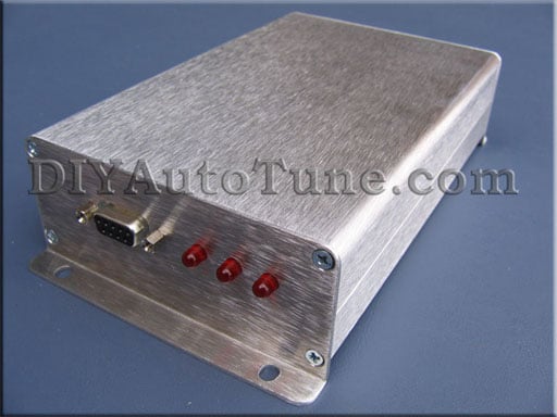
Other options are MS2 V3.57 board
ms2357-c_lg.jpg


Or the now ever popular DIY PNP (N76 model for the 4efte) from DIY autotune
diypnp_n76.jpg


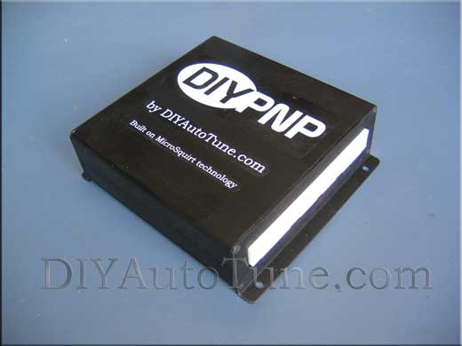
The DIYPNP is very nice and once assembled it is virtually plug and play for your application…..

Now with all that said there are also numerous other circuits you can build to add a lot of extra features to your MS (boost control, nitrous control, egt logging, water injection, launch control / flatshift, and lots more) as the code is constantly being developed.

I won’t go into the specifics of building the MS kit as that information is available at http://www.diyautotune.com and www.ms3efi.com
 

speedfreaq

Member +
Now first step to putting MS on your 4EFTE is the Throttle Position Sensor.
The one found on most 4EFTEs is the square 3pin TPS this will not work with the MS as this is basically just an on off switch which tells the stock ecu if the throttle is open or closed.

Stock sensor
3pin5efhe3.jpg


So you will need to find a throttle body (yes you will need the complete throttle body) from an automatic 4efte or 5efhe. Or find a way to modify your existing throttle body to accept the four pin TPS. I have not confirmed as yet but I think that the TPS found on the 4efte in the Glanza (EP91) are all four pin types. The TPS found and these engines are round and use 4 pins and are true Variable Resistance sensors so these are the ones that will work with the MS.

Four pin sensor:
5efhe_4pin_tps.jpg


Other options for getting the correct type of TPS is to use a Throttle body from a different engine such as the 4AGE, SR20 or many others….. these would require extra modification to your inlet manifold though…

Now once the TPS is sorted out then you can move one.

If you are using the 4pin TPS from the 4efte or 5efhe then here is a diagram that you can use to get it working with your stock ecu if you need to ever return to the stock ecu without having to remove your throttle body or TPS

TPS.jpg
 

speedfreaq

Member +
Next step is the Crank RPM signal.

The 4efte used a distributor based VR sensor output to the ECU which has two toothed wheels and three VR sensors.
So you are going to need two VR circuits for the MS ECU.

The MS2 V3 and V3.57 boards will have one VR circuit built in so you will only need to build one extra VR circuit.
Extra boards can be ordered in a kit form from www.glensgarage.com or www.jbperf.com


The DIYPNP www.diyautotune.com users will have it all done for them as these will come with both VR circuits. These kits are the best and will look and fit as a stock ecu as well……

Here is the schematic for the circuit you need to build
2ndVRMS2.gif


I ordered the components to build the extra VR circuit and built it into the proto area of my V3 board. With a bit of patience and ingenuity it will fit.
S6300576.jpg


This is a pic of the extra board I bought from www.glensgarage.com fitted into my MS case. These boards also comes with loads of other extra circuits as well for egt. Logging, nitrous control, boost control, water injection, and two extra VR circuits as well.
S6301854.jpg


And this is the bad ass DIYPNP board
diypnp-day2-001_1000.gif
 

speedfreaq

Member +
Next step is to wire up the spark output.
MS will be able to run the single coil and distributor setup of the 4efte but if you are willing to modify your existing stock wireloom then you can configure MS to run wasted spark or even coil on plug setups…

So to run your stock ignitor coil setup you’ll need to do the following mods to your MS board.

5V_pulup.jpg


Now all you need to do is wire in you MS system and start configuring the settings to work with the 4efte.

Here is a wiring diagram of how I did my wiring for my setup..
As well as the stock ecu pinout for the 4efte ECU.
fuelandignmod.gif
 
Last edited:

speedfreaq

Member +
With the wiring I had to build a jumper harness for my MS V3 setup to connect to the stock 4EFTE wiring loom

This is what my jumper harness looks like.

S6301859.jpg


Its made from an dismantled stock ECU to get the ecu sockets and basically just matching the pins to where I want them on the DB37 connector

After all that you now just need to setup your ecu to work with the 4efte.
 
Last edited:

speedfreaq

Member +
Just remember that you will need to tune.
I take no responsibility for anyone who uses this info and damages any engine or otherwise….
 
Last edited:

speedfreaq

Member +
how do i upload a file from my computer?

i want to upload my MSQ file which can be used to start and get a stock 4efte up and running
 

ramses974

Member +
i know that MS is wonderfull.. and your thread is well made...
on the mazda mx6 forum they use a lot of MS...and they have crazy power too my other car is a Mazda 626 gd 2.0l 16v turbo Hksgt25 all forged and i am with the emu blue..& an Apexi itc...i know MS is very good
 

350ep70gr

Member +
Massive rep to your side mate!very helpfull!
And top guy to speak with..reply to all my question really fast and with all the needing details.

P.s. The second vr circuit is needed?
Any mod to the distributor tooth wheel as we discuss about?

Chris
 

speedfreaq

Member +
Massive rep to your side mate!very helpfull!
And top guy to speak with..reply to all my question really fast and with all the needing details.

P.s. The second vr circuit is needed?
Any mod to the distributor tooth wheel as we discuss about?

Chris

with the second VR circuit added there is no need to mod the distributor...
just a plug and play install
 
Top