Texx
Super Moderator
System description
Special attention
SRS warning lamp
Operation
Disarm the system
When
How - pyrotechnic pretensioners/airbags 1998 on
How - pretensioners up to 1997
Locking sensor with screwdriver Fig. 1
Disarming pretensioners Fig. 2
Additional procedures
Arm the system
How - pyrotechnic pretensioners/airbags 1998 on
How - pretensioners up to 1997
After deployment
Check
Renew
Disposal
Steering wheel removal and installation
Special attention
Steering wheel and airbag assembly - up to 1997 Fig. 4
Steering wheel and airbag assembly - 1998 on Fig. 5
Spiral cable alignment marks Fig. 3

Tightening torques
Self-diagnosis
Reading codes
Erasing codes
NOTE: The bridge wires MUST be alternated very quickly (within 0,2 seconds).
Fault codes
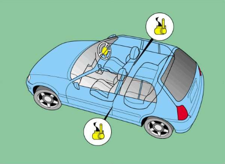
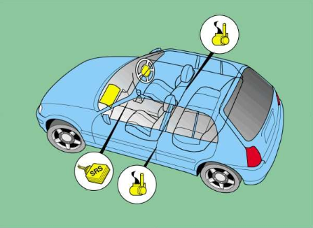
- Optional driver's and front passenger's airbags.
- Airbag locations identified by the inscription 'SRS Airbag'.
- Front passenger's airbag warning label located on side of fascia, passenger's side.
- SRS control module mounted separately.
- Pyrotechnic pretensioners fitted as standard on front seat belts.
Special attention
- To prevent personal injury, expansion area of all airbags MUST remain clear.
- SRS multi-plugs coloured yellow.
- Steering wheel spiral cable has limited rotary movement.
- Centralise steering before disconnecting steering column.
- To prevent damage, ensure steering wheel and spiral cable DO NOT rotate before or during reassembly.
- up to 1997: Pyrotechnic pretensioners are not electrically triggered by SRS control module.
- 1998 on: Pyrotechnic pretensioners are electrically triggered by SRS control module.
- Remove pyrotechnic pretensioner when repairing or welding bodywork near component.
SRS warning lamp
Operation
- Switch ignition ON.
- SRS warning lamp illuminates.
- Lamp extinguishes after approximately 6 seconds.
- If not: Refer to Self-diagnosis section.
Disarm the system
When
- Fascia/instrument panel removal or replacement.
- Front seat belt removal or replacement.
- Repair work around SRS components, especially airbags and pretensioners.
- SRS component removal or replacement.
- Steering wheel/column repair or replacement.
- Welding operations.
- up to 1997: Seat belt removal or replacement: Disarm pyrotechnic pretensioner.
- up to 1997: Vehicle repairs on or near front seat belt: Disarm pyrotechnic pretensioner.
How - pyrotechnic pretensioners/airbags 1998 on
- Ensure ignition switched OFF.
- Remove ignition key.
- Disconnect battery earth lead.
- Make sure accidental reconnection is not possible.
- Wait 1,5 minutes before commencing work.
How - pretensioners up to 1997
- Remove B post interior trim panel.
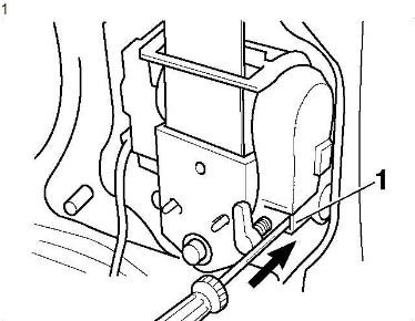
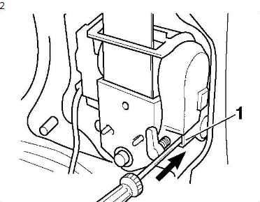
- Using a screwdriver, lock the sensor by pushing in safety lock button Fig. 1 [1].
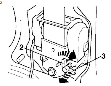
- Turn safety lock release lever from position Fig. 2 [2] 90° clockwise.
- Pull safety lock release lever out to position Fig. 2 [3].
Locking sensor with screwdriver Fig. 1
Disarming pretensioners Fig. 2
Additional procedures
- Disconnect SRS control module when repairing bodywork.
- Disconnect airbag(s) and pyrotechnic pretensioners when repairing or welding bodywork.
- Remove airbag(s), pyrotechnic pretensioners and SRS control module, if temperature is likely to be more than 80°C.
- Remove SRS control module when welding near component.
- Remove pyrotechnic pretensioner when repairing or welding bodywork near component.
Arm the system
How - pyrotechnic pretensioners/airbags 1998 on
- Ensure ignition switched OFF.
- Ensure vehicle interior is unoccupied.
- Reconnect battery earth lead.
- Switch ignition ON.
- Check SRS warning lamp operation.
How - pretensioners up to 1997
- Turn safety lock release lever 90° anti-clockwise.
- Push safety lock release lever in to position Fig. 2 [2].
After deployment
Check
- All mounting brackets for SRS components.
- All SRS components including undeployed airbag(s)/pretensioner(s).
- Fascia/instrument panel.
- Seat assemblies.
- Seat belts, including buckles and anchorage points.
- Steering wheel and column.
- Surrounding components and trims.
- SRS control module fault memory.
- SRS wiring harness and multi-plugs for charred or damaged areas.
Renew
- All deployed or damaged airbags.
- Fascia/instrument panel, if damaged.
- Mounting brackets, if damaged.
- Seat belt(s), if in operation during collision or pretensioner(s) deployed.
- Seat components, if damaged.
- Spiral cable, if damaged or noisy.
- Steering column, if damaged.
- Steering wheel, if damaged.
- Surrounding components and trims, if damaged.
- SRS control module, if damaged or defective.
- SRS wiring harness and multi-plugs, if charred or damaged areas found.
Disposal
- Vehicle manufacturer suggests that deployed SRS components are sealed in a plastic bag and disposed of in accordance with local regulations.
Steering wheel removal and installation
Special attention
- Disarm system and remove driver's airbag.
- Centralise steering before removing steering wheel.
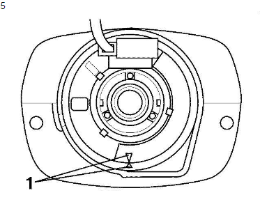
- To centralise spiral cable, slowly rotate anti-clockwise until resistance is felt and then rotate approximately 2½ turns clockwise until alignment marks aligned Fig. 3 [1].
- Ensure spiral cable remains centralised during reassembly.
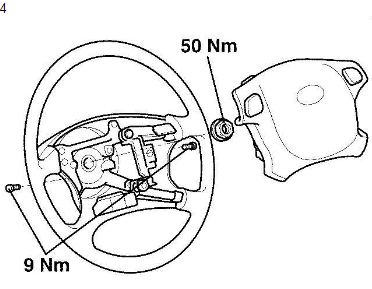
Steering wheel and airbag assembly - up to 1997 Fig. 4
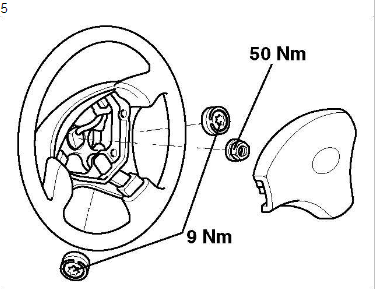
Steering wheel and airbag assembly - 1998 on Fig. 5
Spiral cable alignment marks Fig. 3
Tightening torques
- Driver's airbag 9 Nm
- up to 1997: Front passenger's airbag 5,5 Nm
- 1998 on: Front passenger's airbag 20 Nm
- Front seat 37 Nm
- Front seat belt inertia reel - upper bolt 5 Nm
- Front seat belt inertia reel - lower bolt 41 Nm
- Front seat belt buckle 41 Nm
- Front seat belt lower anchorage point 41 Nm
- Front seat belt lower anchorage rail 41 Nm
- Front seat belt upper anchorage point 41 Nm
- Steering wheel 50 Nm
- SRS control module 20 Nm
Self-diagnosis
Reading codes
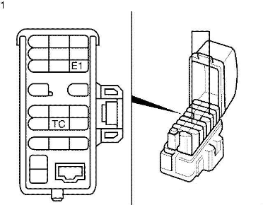
- To access active trouble codes, switch ignition ON and wait approximately 20 seconds.
- Bridge data link connector (DLC) terminals E1 and TC Fig. 1 .
- Count SRS warning lamp flashes.
- Note trouble codes.
- Compare with trouble code table.
- To access intermittent trouble codes, switch ignition OFF.
- Switch ignition ON.
- Wait approximately 20 seconds.
- Count SRS warning lamp flashes.
- Note trouble codes.
- Compare with trouble code table.
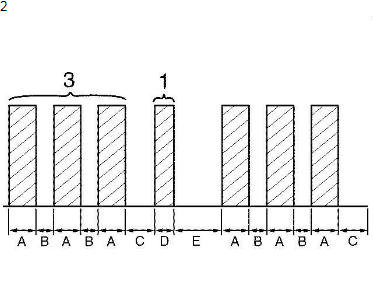
- Each trouble code consists of two groups of flashes Fig. 2 .
- A 0,5 second pause separates each flash Fig. 2 .
[*]A 1,5 second pause separates each group Fig. 2 [C].
[*]Trouble code is repeated after a 4 second pause Fig. 2 [E].
[*]For example: Trouble code 31 displayed Fig. 2 .
[*]Switch ignition OFF. Rectify faults as necessary.
Erasing codes
- Switching ignition OFF should erase trouble codes.
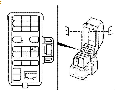
- If not: Connect 2 bridge wires to data link connector (DLC) terminals A/B and TC Fig. 3 .
- Switch ignition ON.
- Wait 6 seconds. Starting with TC terminal, alternately earth TC and A/B terminals twice for a maximum of 1 second at a time.
- Immediately earth TC terminal and leave connected.
- Wait a few seconds, SRS warning lamp should flash erased trouble codes.
- If not: Repeat procedure until trouble codes erased.
NOTE: The bridge wires MUST be alternated very quickly (within 0,2 seconds).
Fault codes
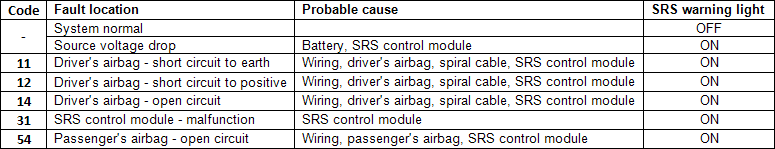
- When the SRS warning light remains lit up and the DTC is the normal code, this means a battery voltage drop has been detected. This malfunction is not stored in memory by the SRS control module and if battery voltage returns to normal, the SRS warning light will automatically go out.
- When 2 or more codes are indicated, the codes will be displayed in numeral order starting from the lowest number.
- If a code not listed on the chart is displayed, the SRS control module is faulty.