madman
Member +
This is not a difficult task, but it is awkward to get at and needs a bit of pateince to get it right.
You will need an electrical multi meter, preferably with small crocodile clips on the end of the leads, a 20 thousand and a 28 thousand inch feeler guage, a star head screwdriver or ratchet socket with star head fitting.
Step 1.
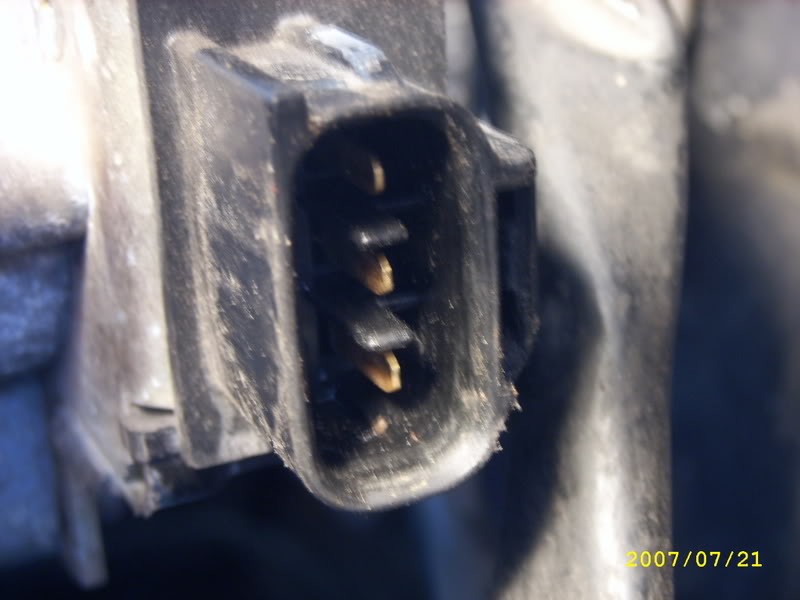
Connect a multi meter to the middle and bottom pins of the TPS connection socket.
This is what the socket looks like.
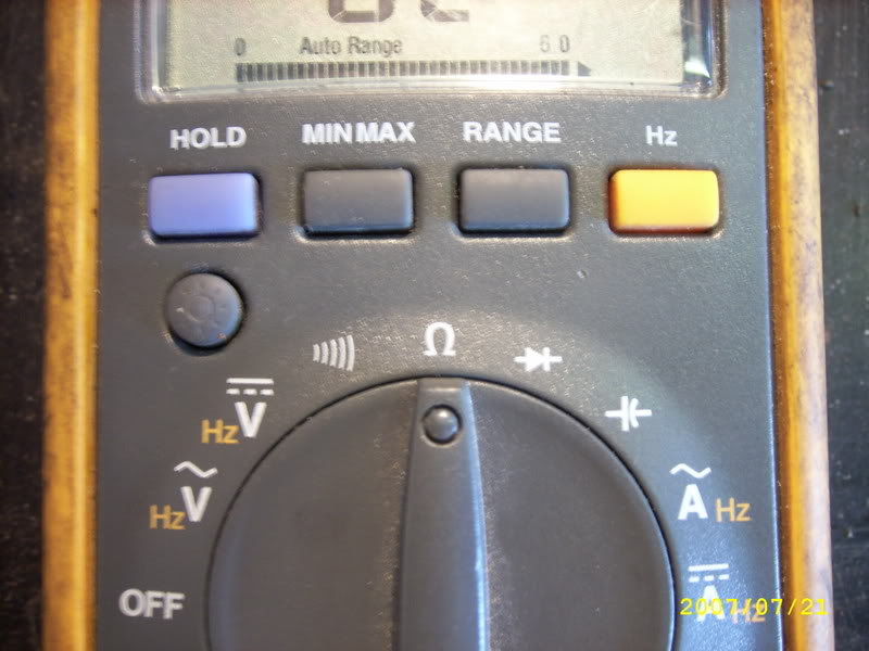
Set the meter to read continuity.
This is the setting for continuity.
Step 2.
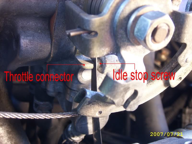
Place a 20 thou feeler guage between the throttle cable connector stop lever and the idle stop screw.
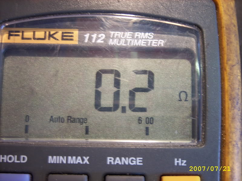
The meter should read that there is continuity and the switch is closed.
This is what the continuity reading looks like. (may vary depending on meter)
Step 3.
Replace the 20 thou feeler with a 28 thou one and check continuity again.
There should be none this time so the switch should be open.
This is what the reading for no continuity looks like.

Step 4.
Remove the multi meter connection from the bottom pin of the TPS connector and replace it on the top pin.
Step 5.
Open the throttle fully and check for continuity again. There should be a circuit this time so the switch should be closed, showing continuity.
If you do not have the correct setting I have found the easiest way to set the sensor is this.
Step 1A.
Connect the multi meter to the middle and bottom connections of the TPS connector.
Step 2A.
Place a 28 thou feeler between the throttle cable connector and the idle stop screw, checking for no continuity.
Loosen the top and bottom screws that fix the TPS sensor to the throttle body.
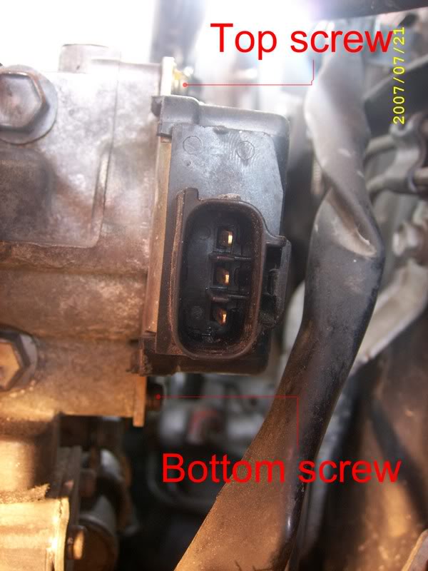
This is a bitch to get at. You need either a star head screw driver bent 90 degrees or a small ratchet with a star head bit fitted to it.
Keep the bottom screw tighter than the top to make it slightly tight to move the sensor.
Step 3A.
Twist the complete TPS sensor unit until the meter reads continuity in these conditions.
Then turn the sensor the opposite direction until the meter just looses continuity.
Tighten the screws up.
Step 4A.
Recheck the sensor again as in steps 1 to 3, sometimes the sensor moves as the screws are being retightened.
Step 5A
If the sensor continuity readings are right at this stage then move on to steps 4 and 5.
If you cannot get the sensor to read correct from just moving its position on the throttle body, it is possible that the sensor has been damaged inside the cover. This is easily done when removing and refitting an engine or inlet maniflod.
Inside the swirch is 3 copper strips and a cam type switch. You can move the copper strips so as they are activated by the cam switch at different times, but it is not easy to do at the best of times, and impossible with the manifold on the car, so it needs to be removed.
You will need to remove the manifold to replace the sensor anyway, so if you feel confident in your abilities give it a go.
This sensor not being set right can cause several problems when the car is at idle, as the ECU will not know if the throttle body is closed fully or just cracked open.
Thanks to weeJohn for this information.
You will need an electrical multi meter, preferably with small crocodile clips on the end of the leads, a 20 thousand and a 28 thousand inch feeler guage, a star head screwdriver or ratchet socket with star head fitting.
Step 1.
Connect a multi meter to the middle and bottom pins of the TPS connection socket.
This is what the socket looks like.
Set the meter to read continuity.
This is the setting for continuity.
Step 2.
Place a 20 thou feeler guage between the throttle cable connector stop lever and the idle stop screw.
The meter should read that there is continuity and the switch is closed.
This is what the continuity reading looks like. (may vary depending on meter)
Step 3.
Replace the 20 thou feeler with a 28 thou one and check continuity again.
There should be none this time so the switch should be open.
This is what the reading for no continuity looks like.
Step 4.
Remove the multi meter connection from the bottom pin of the TPS connector and replace it on the top pin.
Step 5.
Open the throttle fully and check for continuity again. There should be a circuit this time so the switch should be closed, showing continuity.
If you do not have the correct setting I have found the easiest way to set the sensor is this.
Step 1A.
Connect the multi meter to the middle and bottom connections of the TPS connector.
Step 2A.
Place a 28 thou feeler between the throttle cable connector and the idle stop screw, checking for no continuity.
Loosen the top and bottom screws that fix the TPS sensor to the throttle body.
This is a bitch to get at. You need either a star head screw driver bent 90 degrees or a small ratchet with a star head bit fitted to it.
Keep the bottom screw tighter than the top to make it slightly tight to move the sensor.
Step 3A.
Twist the complete TPS sensor unit until the meter reads continuity in these conditions.
Then turn the sensor the opposite direction until the meter just looses continuity.
Tighten the screws up.
Step 4A.
Recheck the sensor again as in steps 1 to 3, sometimes the sensor moves as the screws are being retightened.
Step 5A
If the sensor continuity readings are right at this stage then move on to steps 4 and 5.
If you cannot get the sensor to read correct from just moving its position on the throttle body, it is possible that the sensor has been damaged inside the cover. This is easily done when removing and refitting an engine or inlet maniflod.
Inside the swirch is 3 copper strips and a cam type switch. You can move the copper strips so as they are activated by the cam switch at different times, but it is not easy to do at the best of times, and impossible with the manifold on the car, so it needs to be removed.
You will need to remove the manifold to replace the sensor anyway, so if you feel confident in your abilities give it a go.
This sensor not being set right can cause several problems when the car is at idle, as the ECU will not know if the throttle body is closed fully or just cracked open.
Thanks to weeJohn for this information.
Last edited by a moderator: