alotofpower
Fresh Recruit
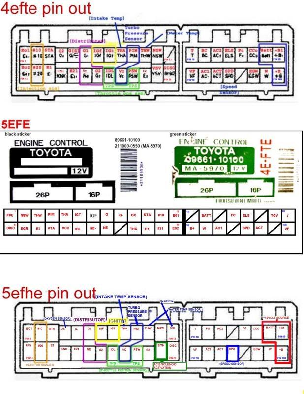
sorry if im gonna annoy anyone but its all a puzzle and im no good at it. im doing an engine conversion from 4e-fe to 5e-fhe in a 95 m/t ep82, ive found ecu pin out diagrams for both and im just having problems putting them together, im using 4e-fe wiring loom and TRYING to wire in the 5e-fhe coilpack.
4e-fe m/t is as follows;
1
2 neutral starter switch
3 water temp. signal
4 pressure intake manifold
5 intake air temp.
6 ignition timing
7 ignition feedback from ignitor coil
8 distributor
9 distributor crank angle
10 oxygen sensor
11 crank signal (starter switch)
12 injector pulse 1&3
13 computer ground
14
15
16 sensor ground
17 throttle position sensor
18 throttle position sensor (pin 1)
19 throttle position sensor (signals ecu throttle position is at idle)
20
21
22
23 vacuum switching valve
24 computer ground
25 injector pulse 2&4
26
5e-fhe m/t is as follows;
1 vacuum switch valve
2 neutral starter switch
3 water temp signal
4 pressure intake manifold
5 intake air temp
6 ignition timing
7 ignition feedback from ignition
8 distributor
9 distributor crank angle
10 oxygen sensor
11 crank signal (starter switch)
12 injector pulse 1&3
13 computer ground
14 aux control valve or idle up system vacuum switch valve
15
16 sensor ground
17
18 throttle position sensor (pin1)
19 throttle position sensor (signals ecuthrottle position is at idol)
20 distributor
21 intergrated ignition assembly
22 sensor ground
23 knock sensor
24 computer ground
25 injector pulse 2&4
26 computer ground
now as far as i can see the only differences are;
pin 1,7,14,17,20,21,22,23,26
but what to do next is not easy to figure out on my own, can someone put the puzzle together for me like this;
4e-fe - 5e-fhe
1 - ?
7 - ?
14 - ?
17 - ?
20 - ?
21 - ?
22 - ?
23 - 1
26 - ?
i hope this isnt asking too much but my eyes are going funny from looking at wires and i dont want to blow the ecu or set the car on fire!!!!!
thanks in advance,
alan
 ok just to update where i am now......