MATTYBYRNEgt2008
Member +
i no this is a common thread ere but we wired it up exactly as diagram and intructions say and theres not a single thing happening???
Last edited:
did you solder it or crimp the wires?
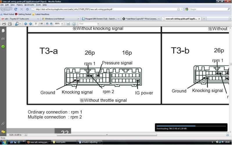
red wire (power) = connecter 2/9
green wire(rpm signal)=connector 1/21
gray wire(throttle signal)=connector 1/19
brown wire(ground)=connector 1/13
black wire (ground)=connector 1/13
yellow wire(pressure signal out put)=connector 1/4
white wire(pressure signal input)=connector 1/4
and i put the brown closer to the ecu and all
iv now read some of these are wrong but live and ground are right and still nothing happened when switched on ignition
use this mate

just ignore the FCD, i wired mine like that a week or so ago, and it worked fine
heres where things get messy i hav a jam fcd??
scotish i hav a wiring diagram ere in front me and it says connector1/13 E01 computer ground
then for connector 1/24 E1 computer ground
i believe the jam fcd, has the same wires as the fcd?? i dont know how compatable the JAM fcd, is with the SAFC. i know the hks one is, but the jam one, im afraid some1 more knowledgeable will have to tell you
My fcd is either JAM or Greddy (can't remember which) and it works fine with the safc.
mine worked fine too.
take it of dude and just connect positive and negative directly to your battrey so you can rule out if its fucked or no!
thats wrong
brown the earth, is connector 1, pin 24, black to the same pin
red wire (power) = connecter 2/9
green wire(rpm signal)=connector 1/21
gray wire(throttle signal)=connector 1/19
brown wire(ground)=connector 1/13
black wire (ground)=connector 1/13
yellow wire(pressure signal out put)=connector 1/4
white wire(pressure signal input)=connector 1/4
and i put the brown closer to the ecu and all
iv now read some of these are wrong but live and ground are right and still nothing happened when switched on ignition