turbosmart Eboost 2 rpm issue

is the stock ignition system "square wave",,,if not, what is it??

i have an electronic boost controller (eboost2) which stated that to run the rpm connection i need a square wave connection..i need to know if this can work with the stock starlet system...here are the exact words from the manual

"""""""The e-Boost2 is able to accept an RPM signal in the form of a square wave that is switching between 0V and 3.5-12 v
The following points should be followed to connect your RPM signal to the negative terminal of an ignition coil. NOTE: Caution should
be exercised when connecting to the negative terminal of an ignition coil and Turbosmart recommends an ECU connection where
possible. IMPORTANT! The RPM signal should not be connected to a coil of a capacitive discharge ignition (CDI) system.
- Check the signal from the negative terminal is a square wave that is switching between switching between 0V and 3.5-12 volts with
an appropriate meter.
- Connect the wire RPM signal wire from the e-Boost2 to the negative terminal of an ignition coil."""""""""

i assume this is IGF on the EP91 ECU connection (#3 pin on 26 plug - IGF Ignition Feedback from the Ignitor-Coil), but when i connect to this wire, the eboost rpm display reads randomly/incorrectly

has anyone got the eboost2 rpm reading to work on their ep82/91??

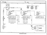
below are the EP91 ignition wires according to the ecu pin out (26 plug)
pin 3 IGF Ignition Feedback from the Ignitor-Coil
pin 4 NE Part of the IIA (Intergrated Ignition Assembly) (RPM)
pin 5 G1 Distributor
pin 17 G- Distributor Crank Angle
pin 18 G2 Distributor
pin 22 IGT Ignition Timing


any help appreciated...maybe i used the wrong pin, but pin 3/IGF works great on my gizzmo shift light
 

Texx

Super Moderator
The igniter should have an output that feed's the tacho, it could be worth hacking into that and see what happens. Unfortunitely, I'm not sure which pin or wire colour you need to be looking for, although a plain black wire rings a bell for some reason.
 

Texx

Super Moderator
Does the EP have an IG- connection in the diagnostic port? That's usually a connection to the coil negative, you could also try that.

I so wish I had some legible wiring diagrams, would save a lot of guessing.
 

Texx

Super Moderator
ep91dlc.jpg
 
just in case...my car is an EP91

http://homepage.ntlworld.com/dub.se7en/TGTT/TOYOTA_ECUS.pdf

hey texx
pages 5 and 6 have ep91/glanza wiring diagrams
pin 4 is NE Part of the IIA (Intergrated Ignition Assembly) (RPM)-----what does NE mean??...

i guess this may be worth a try

i see you have also put it in one on the diagnostic port......maybe a negative coil

i could try these.....what i will do is borrow a multimeter and test the wires.....i would have to wait till w/end to get a multimeter though

i dont want to risk damaging the eboost2,,,by randomly hooking up to wires:haha:......

if u are sure about which wire, then it makes life easier:)

thanks...rep added:rockon:
 

Texx

Super Moderator
Ne is basically the engine speed or crankshaft angle AC voltage waveform signal. Although the ECU can determine engine RPM from it, the ECU has to convert the signal using a analogue to digital converter, so it will be no good for your application.

I would think your best option is to try and find the tacho output from the igniter, as that should have a DC voltage square waveform, it will just depend on whether it matches the signal that the Eboost 2 expects. I wouldn't have thought it would cause any damage if the signal does not match, but only give an incorrect RPM reading from the Eboost 2.

Failing that, hook a meter up between IG- and E1 and see what the maximum voltage reads, you may want to pull the fuel pump relay so the engine doesn't start as I doubt a regular meter will update quick enough to show the voltage change with the engine running.

If you want some background information, there are a fair few Toyota technical articles here if they're of any interest to you:

http://www.autoshop101.com/autoshop15.html
 

Jay

Admin
Been scanning through a few diagrams there, not really sure if which signal is which (can't read jap and the UK books are crap).

I'm looking for the ignition feedback aren't I Terry? I'll assume the Ne feed is of no use.
 

Texx

Super Moderator
I would have thought the Igniter would have an output signal specifically for the tacho. On some of Toyota's systems this same signal is also sent to the aircon control unit, my understanding of this is to give the A/C unit some indication of A/C compressor speed so it can cut the clutch at high revs.

I'm putting a bit of an educated guess into this, but the 5 wires from the igniter will consist of:

IGN (Ignition positive)
IG- (Ignition coil negative)
IGT (Ignition trigger)
IGF (Ignition feedback)

The remaining wire will either be an additional grounding to backup the component ground of the igniter, or in my guess a tacho feed signal.

The IGT signal will have a square type waveform, but the IGF signal is likely to have a non-linear sawtooth type waveform which will probably explain the random RPM reading from the Eboost 2. The IGF pulse matches the IGT pulse in timing only, the voltage of the IGF will rise disproportionate to the length of the pulse, where as the IGT being a square wave will have a controlled constant voltage for the entire length of the pulse.

My guess is that if you wired the Eboost 2 to the IGT output of the ECU, it would probably give a correct RPM reading, but I'm not sure what impact it could have on ignition timing. I suppose you could connect it through a diode which may stop any possible feedback or interferrance.

I'd still be checking that remaining rogue wire from the igniter as it could provide what the Eboost 2 requires, but if not then the IGT signal is going to be the last resort.
 

Texx

Super Moderator
I so wish I could edit posts! :mad:

My guess is that if you wired the Eboost 2 to the IGT output of the ECU, it would probably give a stable RPM reading

That should have read stable as the IGT signal may still not give what the Eboost 2 requires to for a correct RPM reading.
 
ok texx....thanks for the help so far..:rockon:
well..i tried the IG- in the diagnostic box this evening....it still reads incorrectly, but not a incorrectly as the IGF i had it connected to at first

so that 's two wires gone off the list--IG- and IGF...lol

according to hoodey's site""""The toyota ignitor has five wires. These are Battery Positive,IGT,IGF,Tachometer and Coil Negative. The trigger to the ignitor goes from low to high. An MSD must be triggered from low to high."""
http://www.bajanchameleon.com/ultimate.html

and according to this site
http://www.toymods.net/forums/showthread.php?t=10003&highlight=ignitor+wiring

So here are the pinouts, and most comon wiring colours.
Note that the metal case is the earth for the ignitor, so make sure it is bolted to metal (the stock brackets usually provide this earth)

1/ B-R: Coil Negative (output)
2/ B: Tacho signal (output)
3/ B-O: Ignition power (12V+)
4/ W: IGt (input)
5/ W-R: IGf (output)

BOTH sites confirm that the 5th wire should be a tacho wire

just now to find it

also, from my vast readings over the last few days on this topic,,,,it seems the ignotor casing is used to assist in grounding the unit...which also points to the 5th wire being a tacho signal

would this signal be DIRECT to the tachometer---meaning that there is no ecu wire for the tacho??

PS--thanks Jay for your assistance also...much appreciated
 
Last edited:

Texx

Super Moderator
..i tried the IG- in the diagnostic box this evening....it still reads incorrectly

That's probably because the IG- has a sine waveform and not a square waveform, so the inconstant voltage is confusing the Eboost 2.

would this signal be DIRECT to the tachometer---meaning that there is no ecu wire for the tacho??

The tacho signal from the igniter should go directly to the tachometer, it will pass though the engine wire harness into the dash wire harness and then into the multiplug on the back of the combination meter. The only problem is whether the wire colour changes when it reaches the dash wire harness.

The easiest way to check for the tacho wire is to disconnect both the igniter and combination meter and check for continuity between each pin in the igniter connector to each pin in the combination meter connector until you get a reading. It's not going to be that difficult to do, just a pain in the ass having to pull the combi meter out to check it.

The IGF signal is basically the IG- signal with the unwanted parts of the waveform chopped out by a transistor in the igniter IGF signal generation circuit. I've checked through every bit of technical information I have got and cannot find anything that relates to specification of the tacho signal. I'm not so sure it's going to have a square waveform though, it may just be another conversion of the IG- signal and so have an analogue waveform. If the tacho feed doesn't work, it leaves you with 2 choices, connect the IG-, IGF or tacho signal to the Eboost 2 via an analogue to digital converter or use the IGT signal. I'd just be a little reluctant to hack into the signal that controls spark advance.
 
well....texx....i certainly appreciate your efforts ....i mean u have gone out of your way IMMENSELY to help me..........thanks boss:cool:

i will let u know the outcome soon....i'm still not too happy about tapping the IGT wire :haha:...so will see how things play out
 

Texx

Super Moderator
My understanding of micro electronics is a little limited, but I think an Opto-isolator works similar to a relay, but instead of using an electro magnet and switch contacts, it uses a light-emitting diode (LED) and a photodetector. The led fires light at the photodetector and when the photodetector detects the light fired, it switches the second circuit on or off depending on the type of gate configurtaion.

I'm not sure if it can have any affect on converting the signal waveform of the IGf to match the IGt, but you could certainly use an opto-isolator to connect into the IGt signal. All you are introducing to the IGt circuit by connecting an opto-isolator between the IGt wire and the Eboost 2 input signal wire is technically connecting the anode terminal of a diode to the IGt signal wire, this should have no affect on the IGt signal. The end result is the Eboost 2 connected to the IGt via light, so no physical connection which means no feedback or interference can occur.

Plus an opto-isolator will be a hell of a lot cheaper than building or buying an ADC that will actually convert the IGf signal to a square waveform.
 

Texx

Super Moderator
4e-fe could be similar:rolleyes:

Have you got any more circuit diagrams like that mate? For any of the circuits?

I'd give you rep for that, but as im connecting through a proxy the rep function doesn't work for me. :(

Can someone rep Gryzor for that diagram please! :)
 

Gryzor

Admin
4e-fe could be similar:rolleyes:
th_4e-fe_Ignitions_wiring_diag.jpg

Thought I was off the mark. have a few more circuit diagrams one for abs..


I'm updating my garage and gonna start filling it with this kind of info time permitting ;)
 
Top