Boost Setup Confusion :S

Rizzy

Member +
Hi, I Have two GT's my first one with a CT9 Setup, with mods such as FMIC and Dump valve, and a recently purchased GT with a GT25R setup, with a FMIC but no Dump Valve, the confusion im having is very simple, the hoses seem to be setup differently for both,

IMG-20110527-00041.jpg


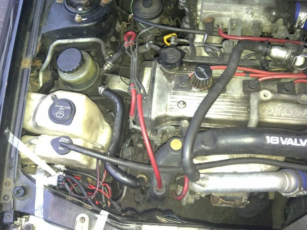
above is the setup on my CT9, as far as i am aware the dumpvalve is setup correctly, its the rest which i need some one to clarify is correct, the middle hose connects to the efi pipe, is this correct, also why does it loop back at the top? is that to bypass the hi/lo solonoid? now the there is a hose coming from the actuator as can be seen closely below, it loops back into another port, is this also correct??

IMG-20110527-00044.jpg


ok now to look at my new GT, it has a GT25 turbo with no dumpvalve of any sort, so i expect it to be different, but im confused as to why they are different,

IMG-20110527-00047.jpg


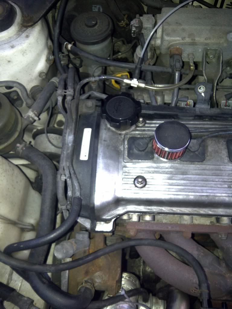
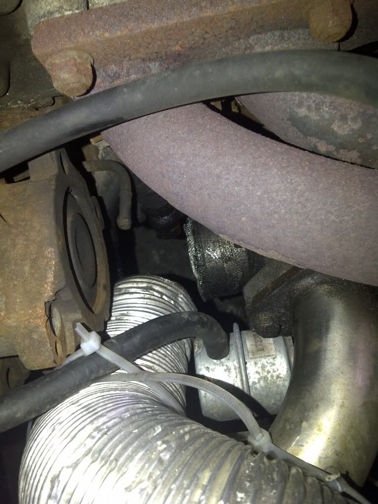
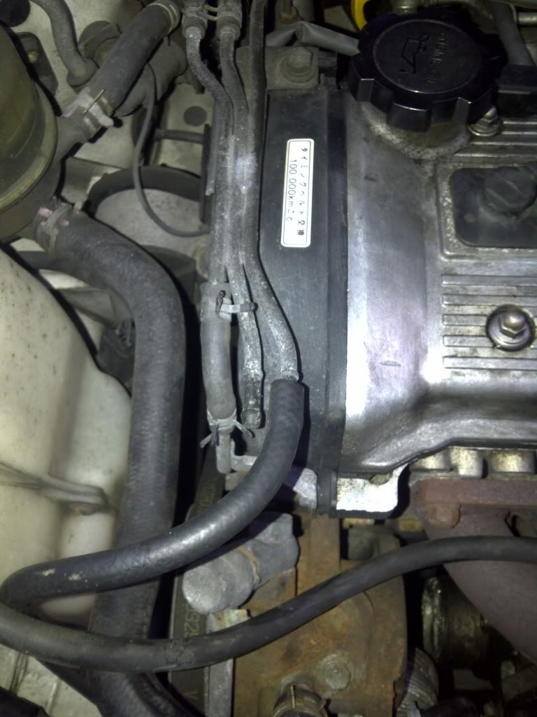
so before we had the actuator looping back into something, now we have an adjustable actuator with the hose going all the way to the top where the dumpvalve is connected in my other GT, the middle hose that connects to the EFi pipe in other setup, is simply missing and not connected to anything?!? the left hose is the same, and at the top it is no longer looped, can anyone explain the differences in the hose piping of the two cars, which one is right or wrong, or maybe both are wrong... or both are fine the way they are im lost....

IMG-20110527-00045.jpg

IMG-20110527-00046.jpg


p.s. ignore the very badly meshed turbo intake, i am well aware of this, previous owner claimed he just didnt have any space to fit a filter, so im working on maybe putting together a home made air filter relocation kit ASAP assuming previous owner was wrong about their not being enough space, either way, in the meantime im getting emergency really fine mesh on their, as the one he used clearly isnt fine enough lol
 
Last edited:

dark_knight

Member +
air lines: how to

hey Rizzy, your setup is pretty straight forward and i hope my explanations will make sense to you. i have made some assumptions since the images did not give all the detail required. follow the links to the edited images i created for you.

instance #1:
your stock BoV has been replaced by an after-market one and thus its' position moved. if you follow the purple arrows, they will show you the air route from the turbo's boost nipple through the actuator (goes under the ps pump in the metal tubing) then surfaces next to the belt side of the block from where it goes towards the firewall and loops back to the EFI (intake). this is primarily for emissions regulations but you as well vent it to the atmosphere like i did.

if you'll also notice from your image, the 3 metal tubing (pipes) lumped together on top of the cam-belt cover are not joined. they are all separate - two of which i've already explained. the 3rd metal tubing/pipe on the extreme right would have been the one carrying the vacuum line from the throttle body to the BoV. i indicated its' possible route via the green line. as you can see in your current setup (even though the image is a little shaved off), i'd presume this line now controls your after-market BoV.

instance #2:
in this shot, i have tried to explain the air route from the turbo to the actuator and after. the turbo compression (boost) side has a nipple that connects to the actuator - which is actually visible here. from the actuator, there is then another pipe (on the reverse side thus not visible here) that connects to the EFI pipe through the long route shown in the previous picture (instance #1). here a shot of a stock actuator removed so that you can see the two nipples mentioned.

instance #3:
in your gt25 turbo setup, you mentioned you have no BoV. if you follow my previous explanations above, you will see that from your throttle body, the t-junction/t-piece splits the vacuum line to what i would presume is a boost gauge - since you mentioned there is no BoV. from the t-piece, it then joins the stock metal tubing on top of the cam-belt cover and comes all the way to the stock actuator. if you will notice in your close-up shot of the actuator, there is a free-hanging pipe to the right of the ps pump. this would under normal circumstance come from the exhaust nipple on the actuator to connect it to the EFI pipe upstream - already explained previously. i would presume your actuator in this case is venting to the atmosphere.

does it all make sense..? let me know if you still need further clarification.
cheers bud.
 
Last edited:

Rizzy

Member +
hey Rizzy, your setup is pretty straight forward and i hope my explanations will make sense to you. i have made some assumptions since the images did not give all the detail required. follow the links to the edited images i created for you.

instance #1:
your stock BoV has been replaced by an after-market one and thus its' position moved. if you follow the purple arrows, they will show you the air route from the turbo's boost nipple through the actuator (goes under the ps pump in the metal tubing) then surfaces next to the belt side of the block from where it goes towards the firewall and loops back to the EFI (intake). this is primarily for emissions regulations but you as well vent it to the atmosphere like i did.

if you'll also notice from your image, the 3 metal tubing (pipes) lumped together on top of the cam-belt cover are not joined. they are all separate - two of which i've already explained. the 3rd metal tubing/pipe on the extreme right would have been the one carrying the vacuum line from the throttle body to the BoV. i indicated its' possible route via the green line. as you can see in your current setup (even though the image is a little shaved off), i'd presume this line now controls your after-market BoV.

instance #2:
in this shot, i have tried to explain the air route from the turbo to the actuator and after. the turbo compression (boost) side has a nipple that connects to the actuator - which is actually visible here. from the actuator, there is then another pipe (on the reverse side thus not visible here) that connects to the EFI pipe through the long route shown in the previous picture (instance #1). here a shot of a stock actuator removed so that you can see the two nipples mentioned.

instance #3:
in your gt25 turbo setup, you mentioned you have no BoV. if you follow my previous explanations above, you will see that from your throttle body, the t-junction/t-piece splits the vacuum line to what i would presume is a boost gauge - since you mentioned there is no BoV. from the t-piece, it then joins the stock metal tubing on top of the cam-belt cover and comes all the way to the stock actuator. if you will notice in your close-up shot of the actuator, there is a free-hanging pipe to the right of the ps pump. this would under normal circumstance come from the exhaust nipple on the actuator to connect it to the EFI pipe upstream - already explained previously. i would presume your actuator in this case is venting to the atmosphere.

does it all make sense..? let me know if you still need further clarification.
cheers bud.


:S I think so... so if I have understood you properly, would i be correct in thinking that I could completely remove the stock metal tubing in the ct9 setup, by directly connecting the piping from the EFi to the pressure line from the stock actuator?

its in regards to my GT25R setup that i start to get lost a little, why is the actuator in this instance connected to the throttle body and not the turbo? is this because a gt25 has no boost nipple like a ct9? is there no longer an exit nipple on underside of the actuator??

finally is it possible for me to add a bov in this setup? if so how? there is nothing in the IC piping for the bov...
 

dark_knight

Member +
air lines: how to

allow me to reply to each of your questions hoping i don't confuse you further.. :)

can i remove the stock metal tubing?
yes, you can completely remove the metal tubing as it's there on stock cars to better manage all the plumbing. when your engine setup changes, you can choose to keep it or trash it. as you can see, all it does is loop the plumbing as it is currently.

why is the actuator connected to the TB?
about your gt25r setup, not sure about it not having a boost nipple but remember, it's the concept behind how it works and not really how it's connected. the typical scenario behind how an actuator works is, it 'reads' boost from the turbo and it will only engage the wastegate open at the point it is set up to, could be nought point 8 bar or 1 bar - all depends on the actuator. now, for it to read boost, you can tap the boost reading from any point post of the compressor wheel. this can be the boost nipple as on a ct9 (which is immediately after the compressor wheel), it can be at the intercooler or even the throttle body. all these areas see positive pressure when you are on boost.

also in the same regard, i would not say there is no longer an exit nipple on the underside of the actuator as the detail from the imaging was a little limited. i can, however, work on the presumption that if it is indeed a stock actuator, then it will have an exit nipple. whether or not it is connected to anything remains the question. if you can and are willing to, you could take it out and check. remember, this exit nipple would in your case just vent to the atmosphere or back into the intake so there is no real 'pressure loss' from it if i may loosely say.

can i add a BoV in this setup?
yes. it is possible to add a BoV in the gt25r setup. again, remember that a BoV is simply a pressure relief valve that helps prevent turbo compressor stall which may occur when you lift off the throttle after a moment of (high) boost. this happens because the compressed air will have nowhere to go to once the throttle plate flaps shut and thus comes back into the turbo. it gives nice chattering sound to some but there have been different schools of thought in this regard so allow me not to delve in.

to add a BoV, you will have to have a vent pipe on the charge side of your setup - charge side meaning either immediately after the turbo as in a stock setup or just before the TB as most fmic setups have. if there is completely no vent/flange in your setup then you may have to consider welding one on in either of the two areas of choice. once set up, connect your BoV to a vacuum line off the TB to enable it read when to vent.

hope that helps..?
ps: if you don't mind my asking, are you new to turbos..?
 
Last edited:

Rizzy

Member +
allow me to reply to each of your questions hoping i don't confuse you further.. :)

can i remove the stock metal tubing?
yes, you can completely remove the metal tubing as it's there on stock cars to better manage all the plumbing. when your engine setup changes, you can choose to keep it or trash it. as you can see, all it does is loop the plumbing as it is currently.

why is the actuator connected to the TB?
about your gt25r setup, not sure about it not having a boost nipple but remember, it's the concept behind how it works and not really how it's connected. the typical scenario behind how an actuator works is, it 'reads' boost from the turbo and it will only engage the wastegate open at the point it is set up to, could be nought point 8 bar or 1 bar - all depends on the actuator. now, for it to read boost, you can tap the boost reading from any point post of the compressor wheel. this can be the boost nipple as on a ct9 (which is immediately after the compressor wheel), it can be at the intercooler or even the throttle body. all these areas see positive pressure when you are on boost.

also in the same regard, i would not say there is no longer an exit nipple on the underside of the actuator as the detail from the imaging was a little limited. i can, however, work on the presumption that if it is indeed a stock actuator, then it will have an exit nipple. whether or not it is connected to anything remains the question. if you can and are willing to, you could take it out and check. remember, this exit nipple would in your case just vent to the atmosphere or back into the intake so there is no real 'pressure loss' from it if i may loosely say.

can i add a BoV in this setup?
yes. it is possible to add a BoV in the gt25r setup. again, remember that a BoV is simply a pressure relief valve that helps prevent turbo compressor stall which may occur when you lift off the throttle after a moment of (high) boost. this happens because the compressed air will have nowhere to go to once the throttle plate flaps shut and thus comes back into the turbo. it gives nice chattering sound to some but there have been different schools of thought in this regard so allow me not to delve in.

to add a BoV, you will have to have a vent pipe on the charge side of your setup - charge side meaning either immediately after the turbo as in a stock setup or just before the TB as most fmic setups have. if there is completely no vent/flange in your setup then you may have to consider welding one on in either of the two areas of choice.

hope that helps..?

yes that 100% helps :) only one bit left, if i was to weld a vent pipe to the FMIC, then add the bov to this, then this bov will now connect to TB if my other setup is to go by, so where would i now connect the actuator? or could i use a t-piece to connect the bov to the TB? or better still if their is an exit nipple on underside of actuator could i connect bov to this?
 
Last edited:

dark_knight

Member +
hose clamps & t-pieces

glad to have been of assistance.. :)

not sure if it was a typo but DON'T weld the vent pipe on your fmic!! much more pressure loss risk if done here instead of some other connecting pipe. weld it post-turbo or pre-throttle body. about connecting your BoV and actuator, you can use a t-piece. the BoV is a closed circuit so there will be no pressure loss even it it's tee'd into the actuator line.

a word of advice though, try and keep your vacuum lines as short as possible but also away from danger- or damage points such as your exhaust mani or other places they can be kinked and snap or split loose. if the pipe does not get a snug fit to the connecting end (for instance, the BoV), use hose-clamps or tie-wraps.
 

Rizzy

Member +
glad to have been of assistance.. :)

not sure if it was a typo but DON'T weld the vent pipe on your fmic!! much more pressure loss risk if done here instead of some other connecting pipe. weld it post-turbo or pre-throttle body. about connecting your BoV and actuator, you can use a t-piece. the BoV is a closed circuit so there will be no pressure loss even it it's tee'd into the actuator line.

a word of advice though, try and keep your vacuum lines as short as possible but also away from danger- or damage points such as your exhaust mani or other places they can be kinked and snap or split loose. if the pipe does not get a snug fit to the connecting end (for instance, the BoV), use hose-clamps or tie-wraps.

lol deffo a typo i meant fmic piping close to either end, as in near where piping fits the TB, or same as my CT9 setup :p

and what are the effects of kinked or split vacuum lines? as i think i saw a split on my ct9 setup whilst taking picture
 

dark_knight

Member +
vacuum lines

nicked or split vacuum lines will cause an erratic or high idle due and boost loss thus not allowing you to hit full boost. ensure your pipes are all mint. they are affordable so you can swap them out for fresh ones. just ensure you get heat & oil resistant pipes - available from most hardware or car accessory shops. you can even get a blend of colors to match your engine bay.. :)
 

Rizzy

Member +
nicked or split vacuum lines will cause an erratic or high idle due and boost loss thus not allowing you to hit full boost. ensure your pipes are all mint. they are affordable so you can swap them out for fresh ones. just ensure you get heat & oil resistant pipes - available from most hardware or car accessory shops. you can even get a blend of colors to match your engine bay.. :)

hmm i will get the lines changed, and see what results i get, thank you very much, i really appreciate the help!! iv learnt and understood sooo much!!

btw a quick ebay search for a decent bov, led me to bump into this, would this be suitable? would avoid the headache of welding? assuming i find the right size.. http://cgi.ebay.co.uk/SILICONE-BOV-T-PIECE-38mm-I-D-25mm-Branch-4-Ply-BLACK-/370497497213?pt=UK_CarsParts_Vehicles_CarParts_SM&hash=item56435f287d#ht_2270wt_905
 

dark_knight

Member +
BoV t-piece

yes of course. that would work. i see you are quick on your feet.. :)
just ensure that you get the correct internal diameters that match your piping - a few mm less (maybe 2 or 3mm) won't hurt so that you get as tight a fit as possible, and since it looks like it will add some 2 or 3 inches to wherever you will add it, you may also want to consider cutting off the same length (or slightly less) from the pipe where you will be fitting it in. don't forget to buy clamps for it if you decide to purchase it.
happy motoring, and hope you are doing this work all by yourself..? that's the spirit of a true tgtt member :D
 

Rizzy

Member +
of course i will be doing it myself, dive right in is my motto lol in fact whilst we have been having this convo....

IMG-20110527-00049.jpg


IMG-20110527-00050.jpg


split vacuum replaced and shortened with clamps :D, stock metal tubing also removed ;)

and as for the IC piping on the GT25...

IMG-20110527-00048.jpg


i think i might just be able to work something out without any welding or cutting!! thanks for the help :p
 

dark_knight

Member +
good one my man. you seem like a handy chap.. :)
all the best with that. while in there, go on and give it a clean will ya! :D
 
Top