Guye
Lifer
I decided to try one of these cheap ebay kits for the convenience of having remote lock/unlocking. The fob actually having a flip out key was also a deciding factor.
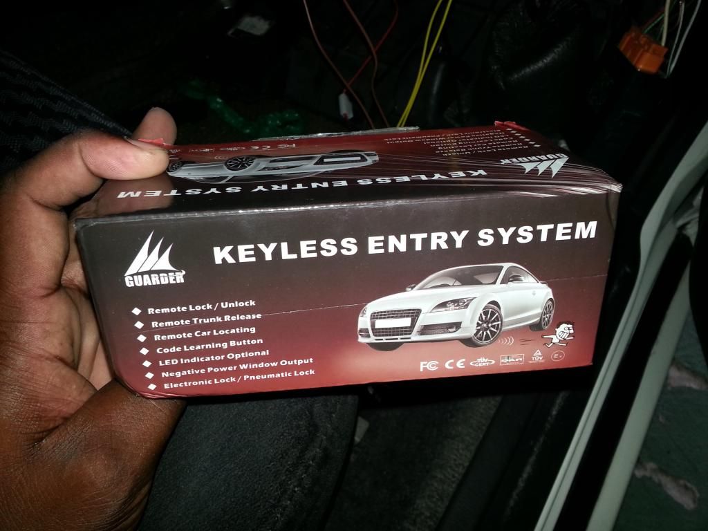
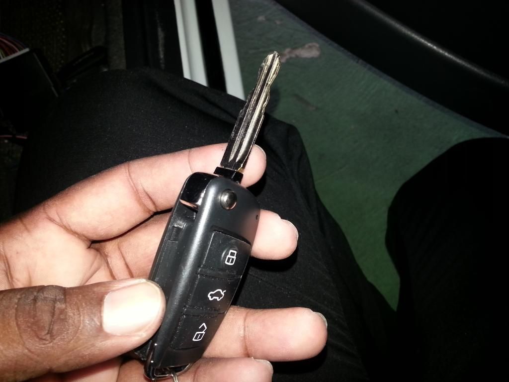
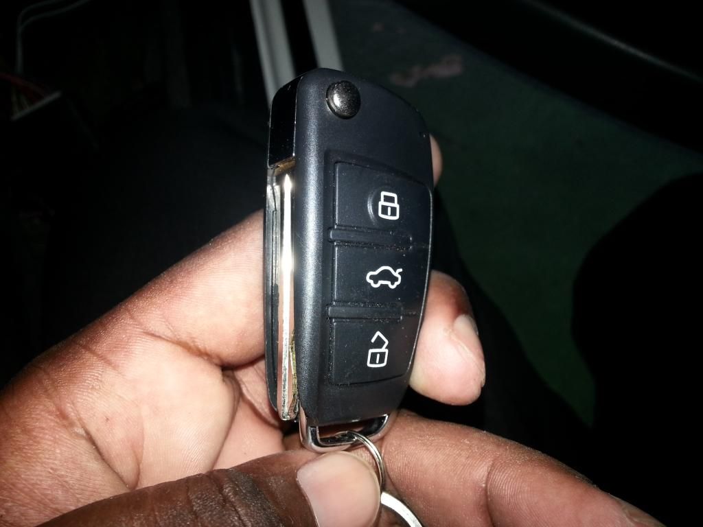
The installation turned out to be very straightforward but since I couldn't find much info for starlet installs I decided to share this for the benefit of anyone doing something similar. First thing to know is that the starlet uses a negative relay based switch system for the factory central locking (ep82, I assume the ep91 is the same). These kits seem to be identical wiring and function wise.
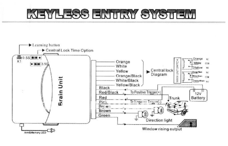
The instructions mine came with were utter rubbish. I only wanted the remote locking/unlocking with the flashing indicators functions, so I isolated and taped up the window, trunk etc. outputs. The flashing led is actually quite annoying and conspicuous so I opted not to use that either.
The correct way to wire for a negative switch system is to attach the yellow and yellow/black wires to ground, white/black goes to unlock signal, white goes to lock signal and the orange wires are unused. Connect the red wire to a constant 12+ and the black wire to ground.
Remove the panel under the steering wheel and locate the factory door lock module. It will be a blue box with an orange connector plugged into it. It's a good idea to remove the bottom half of plastic shroud around the stalks/combination switches at this point as well if you plan to use the flashing indicator feature.
I took the entire door lock module down but you only need to disconnect the harness to tap into the lock/unlock wires.
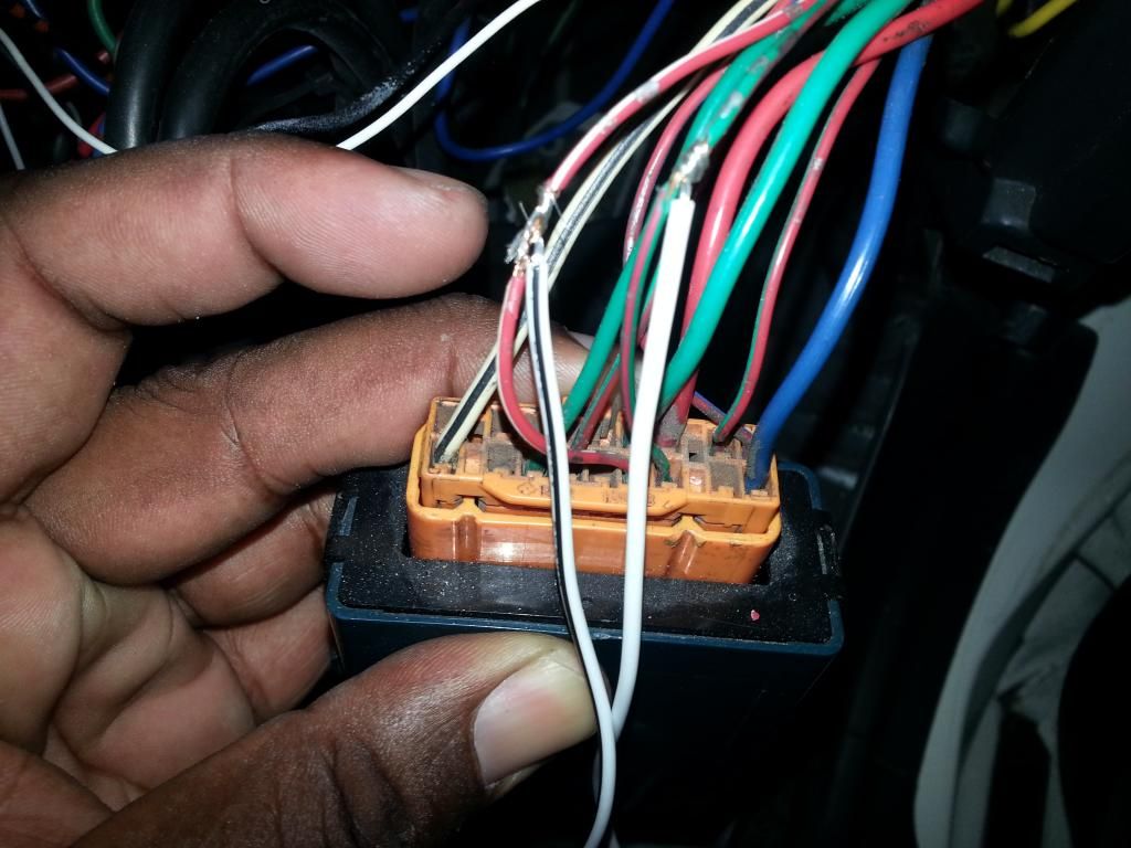
Splice the White/black wire into the red/white wire and the white wire into the green/red wire.
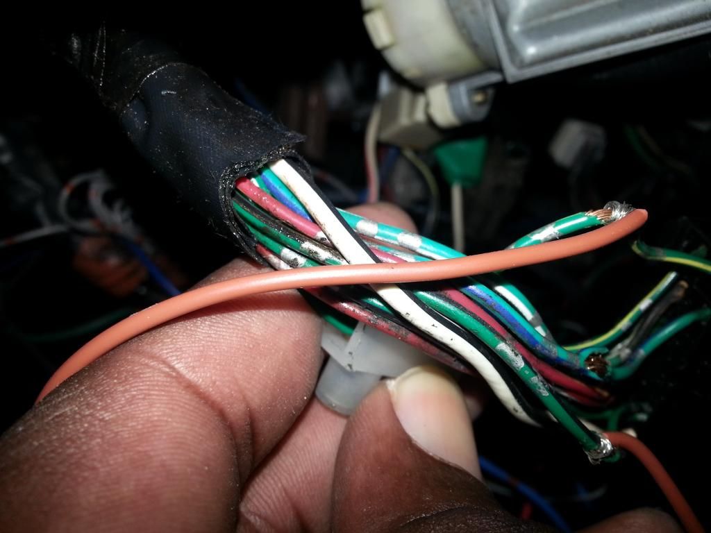
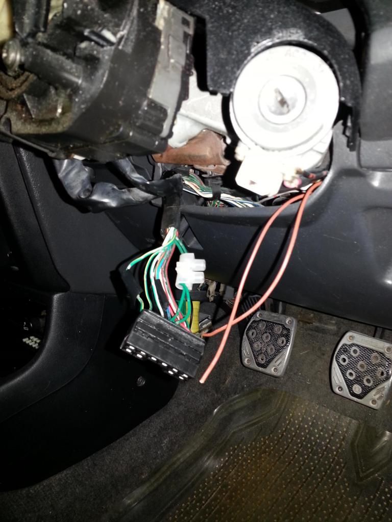
Sorry for the poor pic. Disconnect the black connector from the base of the combination switch and splice the brown wires into the green/yellow and green/black wires to activate the indicator flashes for lock/unlock and car locating.
*EDIT* I drove the car today and found that when I used any turn signal, both would flash like hazard lights. It turns out the brown wires are not powered individually but are linked in a loop. EG. If I connected one brown wire to the green/yellow wire for the right turn signal only and then indicated right that would flash but I would also read +12V on the other brown wire although the "brain unit" is doing nothing. If the second brown wire was connected to the green wire for the left indicator (first row of 4 pins, second from right) the +12v from the green/yellow wire would cause the left indicator to flash also on a right turn signal and visa versa. This means, that at least for the unit I received, wiring it according to directions will interfere with the function of the turn signals. Yet again I do not know if they all function like that (I seriously doubt) or if my unit is faulty. I suppose if I install a diode on each wire it would stop the current from flowing back through the unit...but I cannot be bothered with that right now so I have removed the brown from the unit from the wire for the indicators. To retain a visual indicator that the doors have locked/unlocked I have connected one brown wire to the solid green wire (second row of 6 pins, third from the left) for the park lights instead as this is used by most universal alarm kits. I now get flashes of park/fog lights when locking or unlocking. Yet again, this may not be needed with all remote locking kits but it does seem that generally speaking these Chinese units are all identical function and wiring wise. The change I have made works perfectly for me.
After soldering and taping the wires, plugging in the connectors and selecting a spot to mount the "brain unit" for the remote locking (I stuck mine to the right side under the dash with double sided tape) put your panel and shroud back together and enjoy the laziness.
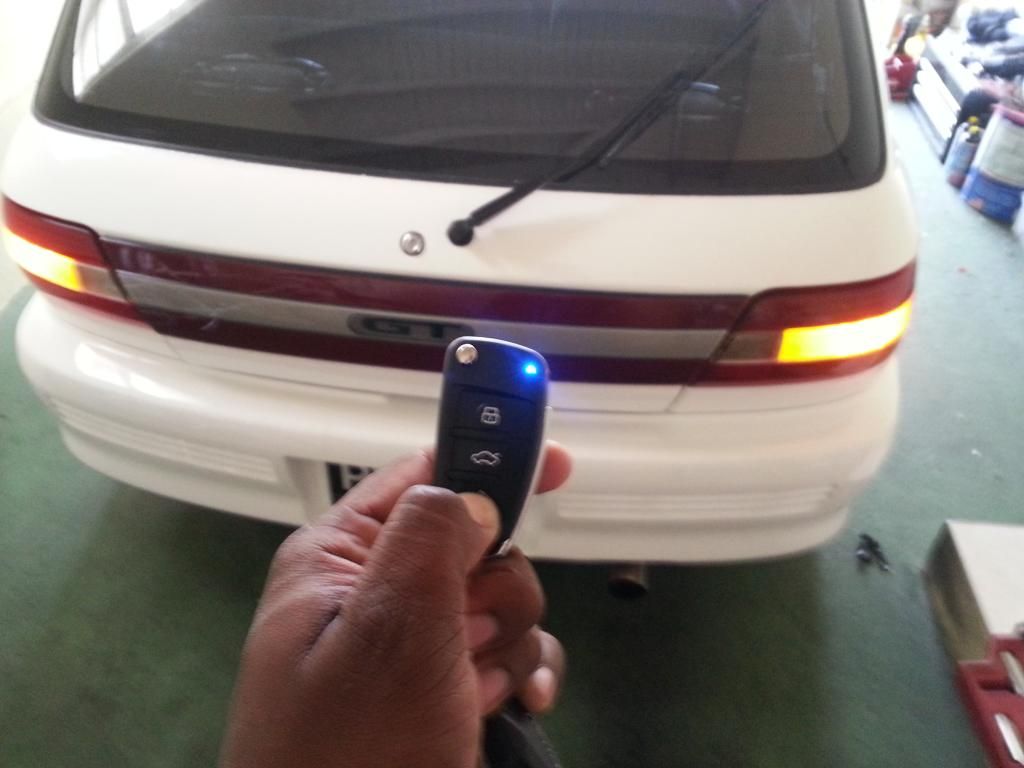
(Park lights flashes instead of indicators now)
UPDATE
I decided to install diodes afterall. I used a pair with the part# IN6406BL. Diodes allow current flow in only one direction thereby sloving the issue mentioned above plus they are dirt cheap to buy.
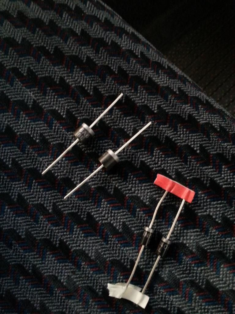
The diodes were installed between the brown wires from "brain unit" and the indicator wires on the harness under the steering wheel/combination switch.
After soldering and taping the connection the flashers now work with the lock/unlock button on the key fob but still function normally otherwise.


The installation turned out to be very straightforward but since I couldn't find much info for starlet installs I decided to share this for the benefit of anyone doing something similar. First thing to know is that the starlet uses a negative relay based switch system for the factory central locking (ep82, I assume the ep91 is the same). These kits seem to be identical wiring and function wise.

The instructions mine came with were utter rubbish. I only wanted the remote locking/unlocking with the flashing indicators functions, so I isolated and taped up the window, trunk etc. outputs. The flashing led is actually quite annoying and conspicuous so I opted not to use that either.
The correct way to wire for a negative switch system is to attach the yellow and yellow/black wires to ground, white/black goes to unlock signal, white goes to lock signal and the orange wires are unused. Connect the red wire to a constant 12+ and the black wire to ground.
Remove the panel under the steering wheel and locate the factory door lock module. It will be a blue box with an orange connector plugged into it. It's a good idea to remove the bottom half of plastic shroud around the stalks/combination switches at this point as well if you plan to use the flashing indicator feature.
I took the entire door lock module down but you only need to disconnect the harness to tap into the lock/unlock wires.

Splice the White/black wire into the red/white wire and the white wire into the green/red wire.

Sorry for the poor pic. Disconnect the black connector from the base of the combination switch and splice the brown wires into the green/yellow and green/black wires to activate the indicator flashes for lock/unlock and car locating.
*EDIT* I drove the car today and found that when I used any turn signal, both would flash like hazard lights. It turns out the brown wires are not powered individually but are linked in a loop. EG. If I connected one brown wire to the green/yellow wire for the right turn signal only and then indicated right that would flash but I would also read +12V on the other brown wire although the "brain unit" is doing nothing. If the second brown wire was connected to the green wire for the left indicator (first row of 4 pins, second from right) the +12v from the green/yellow wire would cause the left indicator to flash also on a right turn signal and visa versa. This means, that at least for the unit I received, wiring it according to directions will interfere with the function of the turn signals. Yet again I do not know if they all function like that (I seriously doubt) or if my unit is faulty. I suppose if I install a diode on each wire it would stop the current from flowing back through the unit...but I cannot be bothered with that right now so I have removed the brown from the unit from the wire for the indicators. To retain a visual indicator that the doors have locked/unlocked I have connected one brown wire to the solid green wire (second row of 6 pins, third from the left) for the park lights instead as this is used by most universal alarm kits. I now get flashes of park/fog lights when locking or unlocking. Yet again, this may not be needed with all remote locking kits but it does seem that generally speaking these Chinese units are all identical function and wiring wise. The change I have made works perfectly for me.
After soldering and taping the wires, plugging in the connectors and selecting a spot to mount the "brain unit" for the remote locking (I stuck mine to the right side under the dash with double sided tape) put your panel and shroud back together and enjoy the laziness.

(Park lights flashes instead of indicators now)
UPDATE
I decided to install diodes afterall. I used a pair with the part# IN6406BL. Diodes allow current flow in only one direction thereby sloving the issue mentioned above plus they are dirt cheap to buy.

The diodes were installed between the brown wires from "brain unit" and the indicator wires on the harness under the steering wheel/combination switch.

After soldering and taping the connection the flashers now work with the lock/unlock button on the key fob but still function normally otherwise.
