Taggys Dummies guide to building a 4e/5efte engine
Note this is my build as of today 22/5/12, so its still being built. I welcome your comments and also if you think i have missed ANYTHING thats worth adding, please comment as i want it as accurate as i can for everyone") .
.
Index
Introduction
Parts required
Machine shop work
Tolerances on critical engine parts
Bottom end assembly
Introduction
So you consider your self a dummy but are keen to build engines and save your self some wonga, then read on. With this guide anyone should be able to build an engine who can follow my instuctions. Its not a black art and is actually fairly easy although it is quite time consuming getting all the measurements correct, in fact you spend more time measuring everything than you do building it! Although most of it is just knowing the correct procedure for everything
I am documenting this on my own forged 5E build
Now UKSC managed to loose my disasembly guide to go with this so this will currently just cover the reassembly, I'll rewrite it after i have put my engine back together! Note everything in here is for reference and I take no responsibility for anything in building your own engine and stuff going wrong, but follow this correctly and you will be fine.
TAKE NOTE!
So first rule of thumb in engine building, DO IT ONCE, DO IT RIGHT!!!!! Dont cut ANY corners and read this document about 10 times before you even start building it so you are familure with the build process. If you cut any of the steps out or rush building it, you may as well throw your money down the pan. Engine building is all about minute tollerances between parts and putting everything back together in a set sequence, thats the pep talk over, let go!!
Parts required for full rebuild
This is based on my 5e forged build, so if your building a standard or 4e obviously buy the respective corresponding parts. I will list the prices I paid also as of 28/3/12 So you can use for reference.
PEC forged 5e connecting rods - £400
74.5mm Wossner forged pistons - £450
Athena MLS 1.2mm headgasket - £100
Toyota full engine gasket set - £148
Toyota oil pump - £97.50
5E conversion flywheel (so you can use the larger 4e clutch) - £140
Water pump - £29.90
Timing belt - £25.50
Engine stand - £55.00
Piston ring compression tool (to fit pisons in the block) £11.98
ACL main bearings - £43
ACL big ends - £36
ACL thrustwashers -£12
Total: £1548.88
Obviously on top of this you need a 5e Donor engine which cost me £125 from a Toyota Paseo and you also need a 4E head and sump/strainer. In hindsight i drastically underated the build cost!!! so thats £1673.88 so far without any workshop costs!!!
Machine Shop work
Now that you have stripped the engine down to its bare parts i.e
Head
Block
Crank
Pistons and rods
We can begin to work on these parts to get them ready for assembly. First things first we need to take our block, head and crank down to the local engineering workshop who will inspect them to ensure they are useable (i.e not damaged) and that they are within tolerance, and if not they can be ground, polished etc.
In particular you need the following work done:
Get the head skimmed
Fit new head valve stem seals (you can do this your self if you have the tools)
Head chemically cleaned
Had the block bored oversize
Bores Cross hatched and honed
Block decked
Block Chemically cleaned
Block notched
Had the crank measured and polished
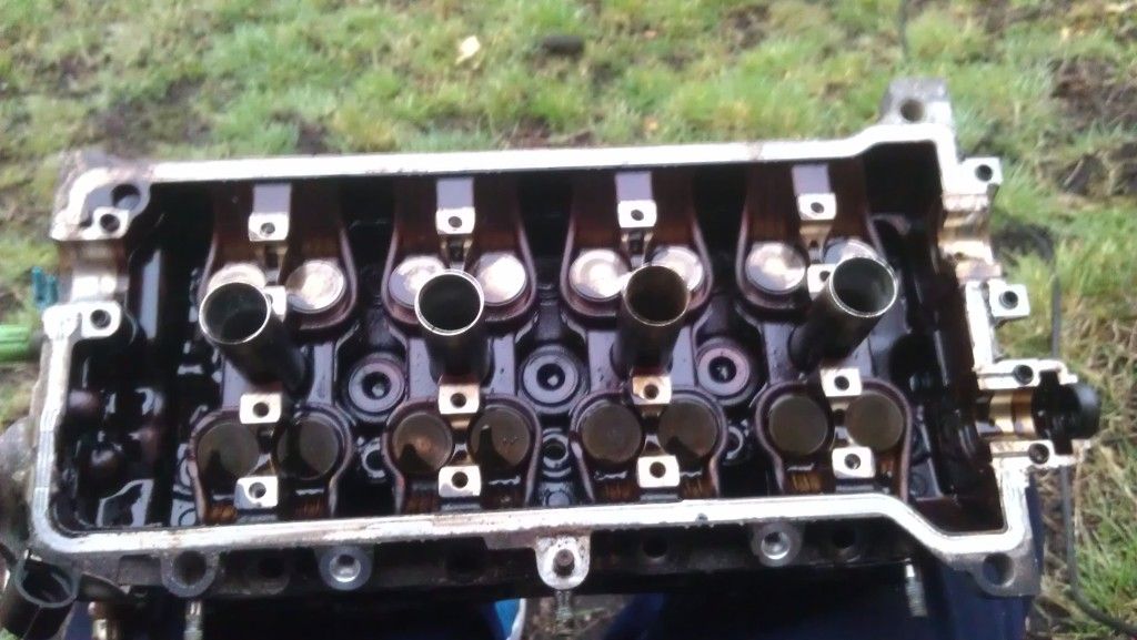
The Head
Before a chemical wash
After Nice clean refreshed head with new valve stem seals
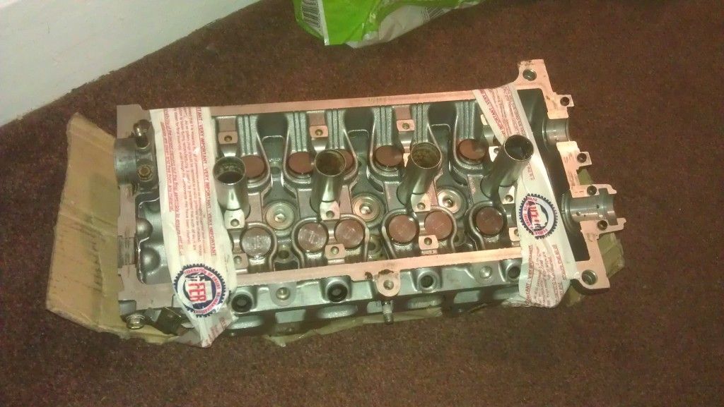
As part of the build you would have bought a full toyota engine gasket set, so when you give them the head ask them the change the valve stem seals for you (unless you have the tools to do it your self) and also check the head to ensure its straight. As a rule of thumb if your spending this much money on it, for the sake of £30 get it skimmed, even if your Head gasket hadnt failed. This way you know 100% the head is totally refurbed when you put it back together, DO IT ONCE DO IT RIGHT!!, It should also be chemically cleaned
So you want to ask for:
Valve stem seals changing (unless you can do it, need a special tool to remove valves)
Head skimmed
Chemically cleaned
possibly ported and polished if they do it.
The Block
The block will need to be cross hatched and honed to fit your standard size pistons, or if you are going oversize then bored out to the size of your pistons. 74.5mm is the common size for forged pistons, or a maximum of 75mm but this give no room for error if you damage the block in future, it will have to be scrapped.
Your new pistons will come with a spec sheet so give this to them. Also ensure you ask to get the block decked to ensure its straight and smooth to reveive the new HG (DONT LEAVE ANYTHING TO CHANCE!!). When you get it back give it a coat of high temp paint for the new look, just make sure you mask it all up It should also be chemically cleaned.
So you want:
Bored oversize if need be if your going oversize pistons
Honed and Cross hatched
Chemically cleaned
Top of the block decked
The Crank
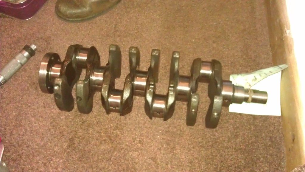
The crank will either be standard size or it may have been skimmed in the past and be undersize, the workshop will check this for you and advise appropiate bearings. Always use ACL bearings for the main bearings, big ends and thrust washers. The crank journals should be free of scratches to be used and its advisable to get it polished, or ground if damaged.
If you dont have the tools to measure the journals your self, get the machine shop to do it, ask them to service the crank, measure it all up to toyota specs and also check for out of roundness.
Work required:
Polished or ground if unserivcable, you can go undersize 0.25 and 0.50
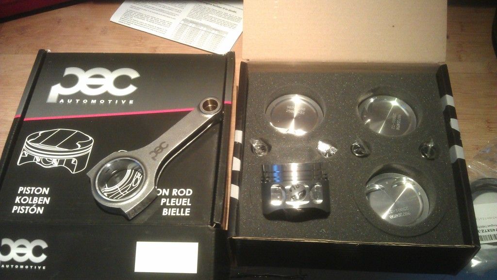
Pistons and rods
Give your pistons and rods to the machine shop and ask them to the attach the pistons to the rods, you will need to give them one of the standard ones so they can see what direction it attaches. I paid the workshop but in hindsight do it your self, i was under the impression you needed a press to do it but you can fit them without one as they just slide in, gutted! oh well
Once your pistons and rods are together you will also need to gap your piston rings acording to the spec sheet provided with your pistons and also you will need to "Clock" your rings so that they are put on in the correct direction. Again your spec sheet will provide you with this information.
Tolerances on critcal engine parts
Dependent on what your circumstances are on rebuilding your engine, you need to get a number of things checked to ensure that your engine parts are within tolerance of the specification as set out by Toyota. This is because parts could be worn out of shape or new parts may not be a 100% fit and so you need to check the specifications and get them spot on. DO NOT IGNORE THIS, IF YOU DO YOUR ENGINE WILL FAIL! In fact this is the most important part of engine building and is the main reason people doing this end up with a knackered engine.
I will post up the spec sheets shorly for the 5e which you need to follow to ensure your engine does not fail prematurely.
This is VITAL and includes
Measuring your existing bottom end bearings - they will either come in standard or oversize if the crank has been ground previously
Measuring your bores - This ensures that they are within specifcation and not worn out of shape past Toyotas recomendations
Measuring your piston ring gaps - Again even new new rings for any pistons need to be gapped,
Measure the crank for out of roundness - Ensure your crank is not worn unevenly which could cause premature bearing failure.
Measuring sideways crank drift - If your thrust washers are worn your crank may have to much sideways play
I'll be posting up more details and pictures of each of these processes this week.
You need accuarate tools to be able to measure most of the above, if you dont have these then you can do what I did and ask your machine shop to measure it all for you. It costs a bit more but its a must!!
Bottom end assembly
Parts Required:
ACL Main Bearings
ACL Big ends
ACL Thrust washers
Assembly lube
Torque Wrench
Micrometer, with telescopic tubes (measure your bores, bearings)
feeler guagues (Gap your piston rings)
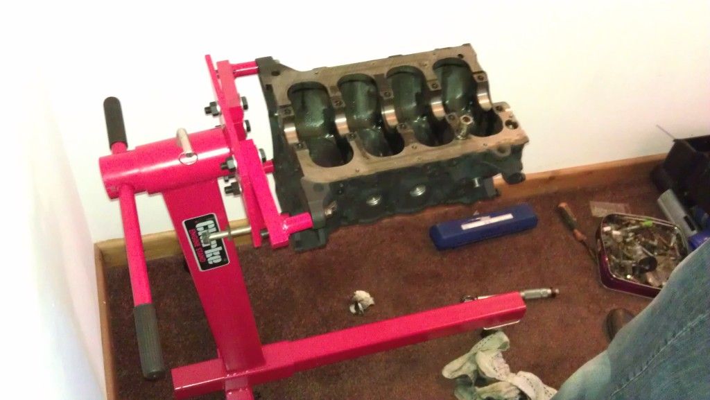
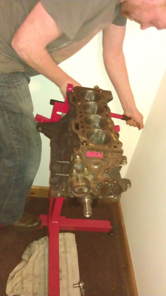
So now you have spent a small fortune to get to this point its time to put it together, dont even think about doing this on a bench or the floor, go out and buy your self an engine stand. You can pick them up for about £50 and it will make things ten time easier as well as keep any dust contaminants away from the engine.
This is mine i bought it from machinemart new online for £55
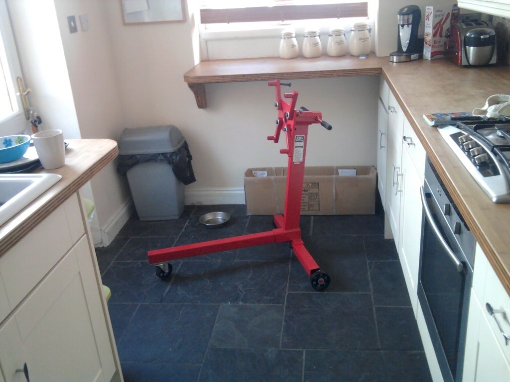
NOTE: IT IS REALLY, REALLY important you build your engine in a clean environment, so your shed aint gonna cut it. One bit of crap in one of the journals, oil ways and the whole bottom end could fail. Build it in your house if your Mrs will let you lol, i went up my mates
Get your block and stick it onto your engine stand like this...
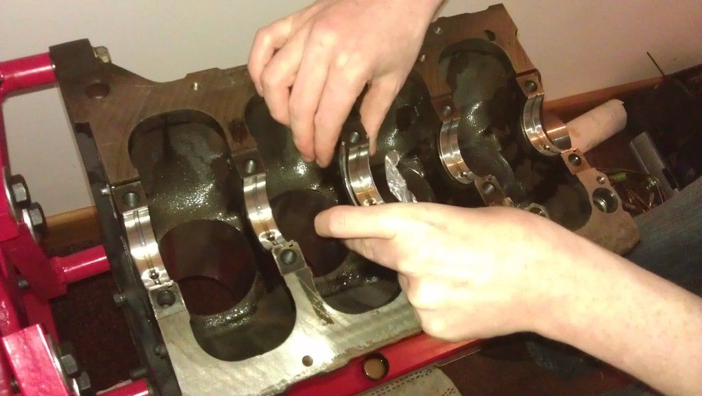
The first job is to fit the main bearings into the block journals, by this point you should have worked out what bearings you need be it standard or oversize.Measure them with a micrometer to find out or ask your workshop. So go get your ACL main bearings and pop them in like below, then line the notches up so then gently press them in to seat them properly. Make sure the journals are clean and free of any contaminants before you put each one in. Do not put any lube on the back of them or the seat.
Click all 5 in as shown below and then put a liberal coating of oil on all 5. "NOTE: DONT USE ENGINE OIL buy Engine Assembly lube" I found that the oil was to thin and after a couple of days it had all ran out the bottom, get some engine lube, its thick as hell and will ensure your engine doesnt scuff anything on initial start up.
Placing the final one in
Once you have put them all in it should look like this
Next is to fit the thrust washers in the centre on number 3 these stop the crank from floating sideways once its all tightened up, the are maked with lines on one side of them, these markings face OUTWARDS on both sides. Note: There are 4 of them, two for the bottom and two for the top, put the two in now coat them in lube so they stick, the other two go in later on.
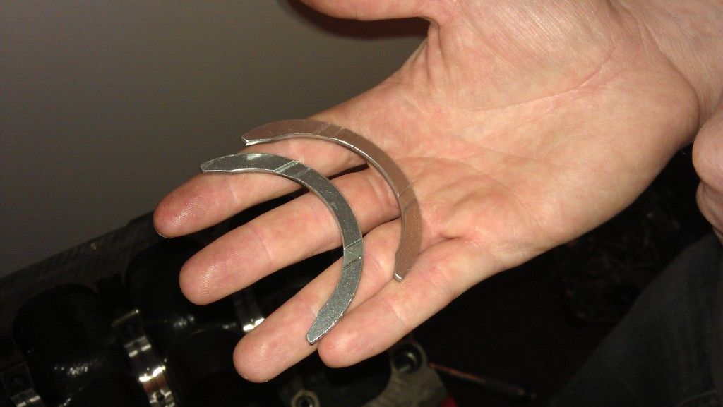
The right one
The left one
Next is to get your polished crank and lube the main journals ready to lower it into the engine. Again coat the main journals in oil first onthe crank.
Lower it in really carefully and ensure its completly horizontal to snugly fit into the journals, you do not need to force it. Note: The crank has to face the correct direction as shown below, the crank pulley side goes the direction of the timing belt.
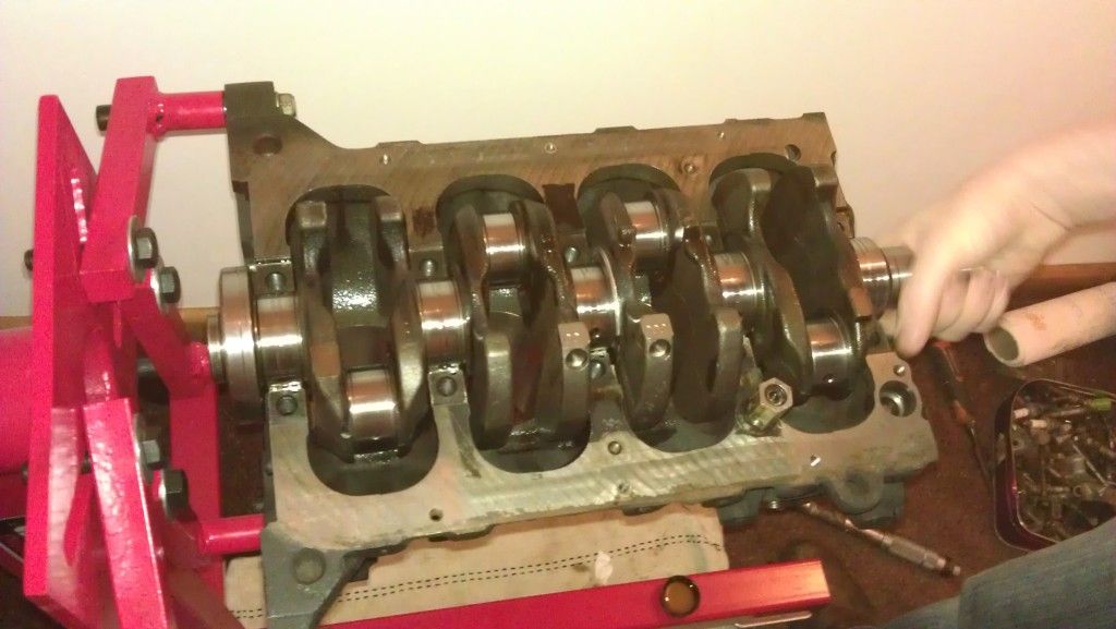
You can give the crank a little turn to ensure its seated properly, just keep an eye on those centre thrust washers as they might move, just make sure they are flush. If all is good it should turn freely with little resistance.
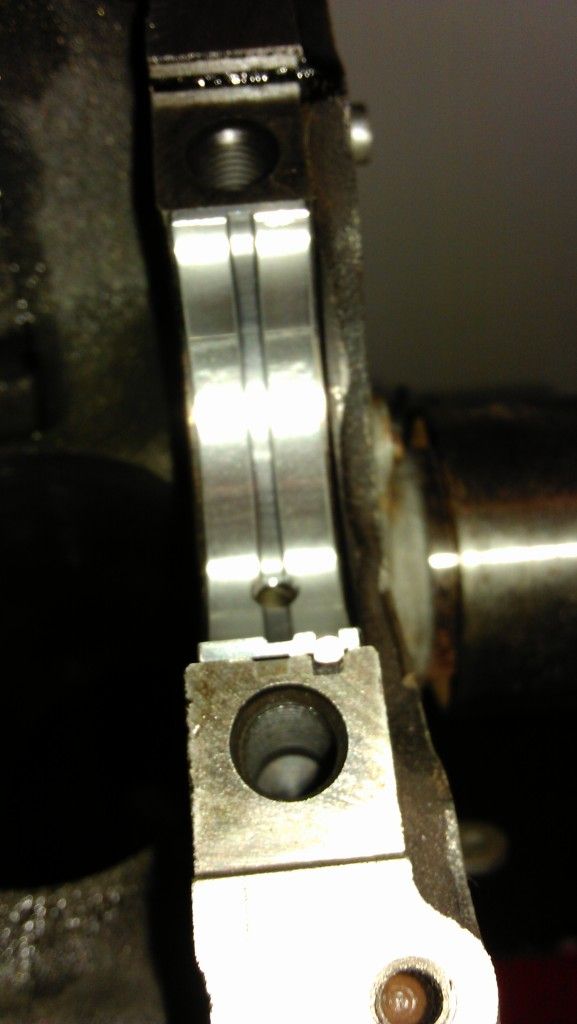
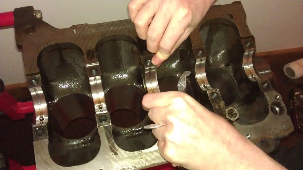
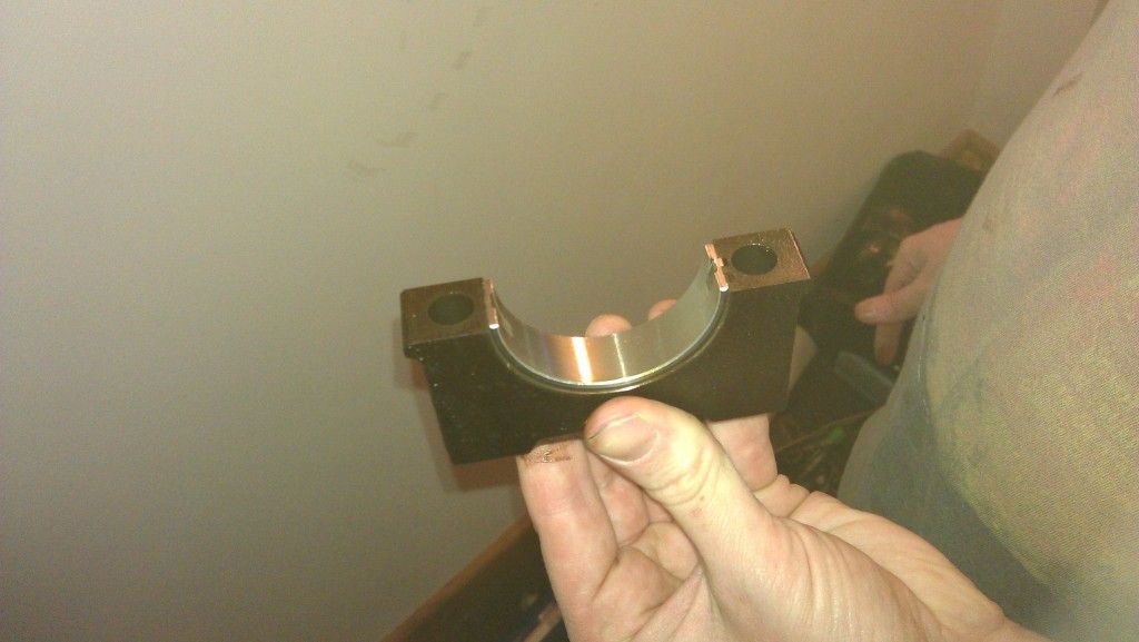
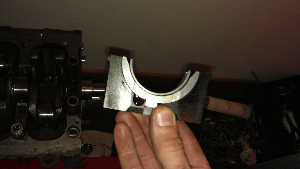
Next is to put the main caps on to hold the crank in place, these also need bearings put into them, there are 5 of of them and they are numbered 1-5, again cover the outside in oil once fitted.. It is very important you put these on the correct way and in the correct sequence. You will notice that each one has a number on the top and also a small peg in the middle to indicate the direction it should go. Number 1 starts on the clutch/flywheel side with the peg facing the timing belt and then 2,3,4,5 all follow the same pointing towards the timing belt side with those pegs.
Grab number 1 and put your bearing in (note the number on top)
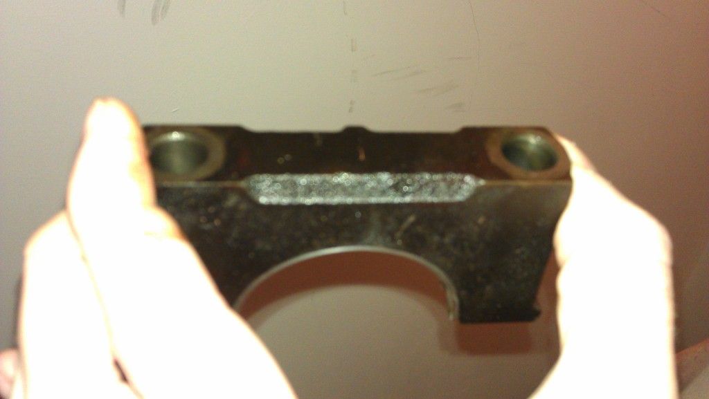
Again like the other bearings, press them in with the notch facing the notch on the cap like above. Dont forget to coat it wil lube after you have put it in
Put all your caps on 1 through 5 (facing the correct way) not forgetting to put the last two thrust washers in number 3, again lube them to help them stick.
and then hand tighten all the crank bolts, make sure the caps sit nicely on top of its seating position ready to be tightened down.
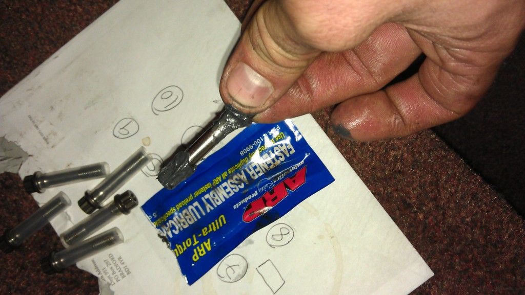
The crank bolts need to be tightened with a torque wrench and need to be done in two stages of tightening. Also its important you put fastner on this bolts like below (follow the insructions for use)
 Set your torque wrench to 24Nm and then tighten them in a set sequence below
REMINDER: ADD TORQUE SEQUENCE DIAGRAM
Once tightened increase the torque setting to 58Nm and again follow the above tightening sequence.
Next rotate the engine as the next stage is to fit your pistons and rods
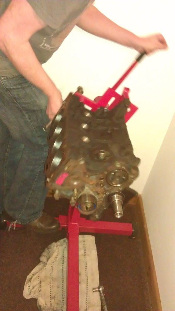
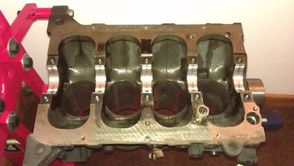
So your engine should now be in this position
Looking down from the top we can see the crank below which is where our pistons are going to be attaching too
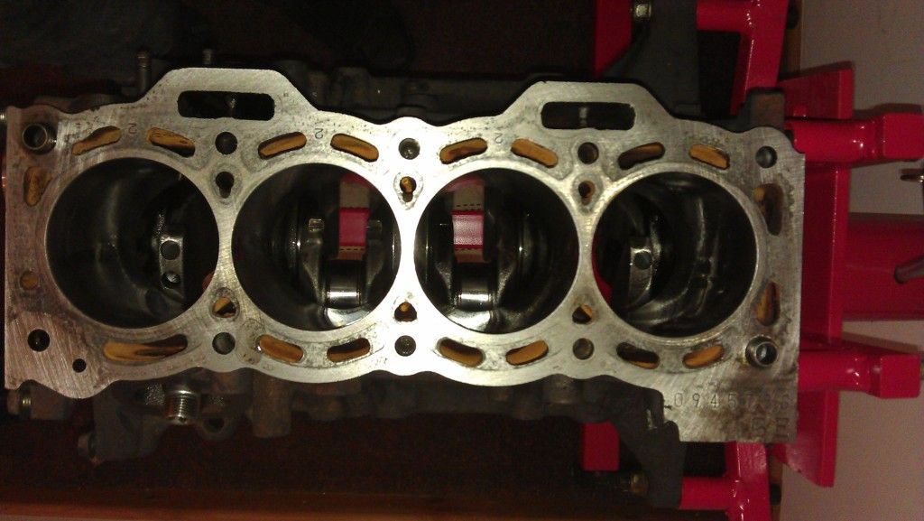
Note to those who noticed the block isnt decked, yes i sent it back, how much better is that!!!!
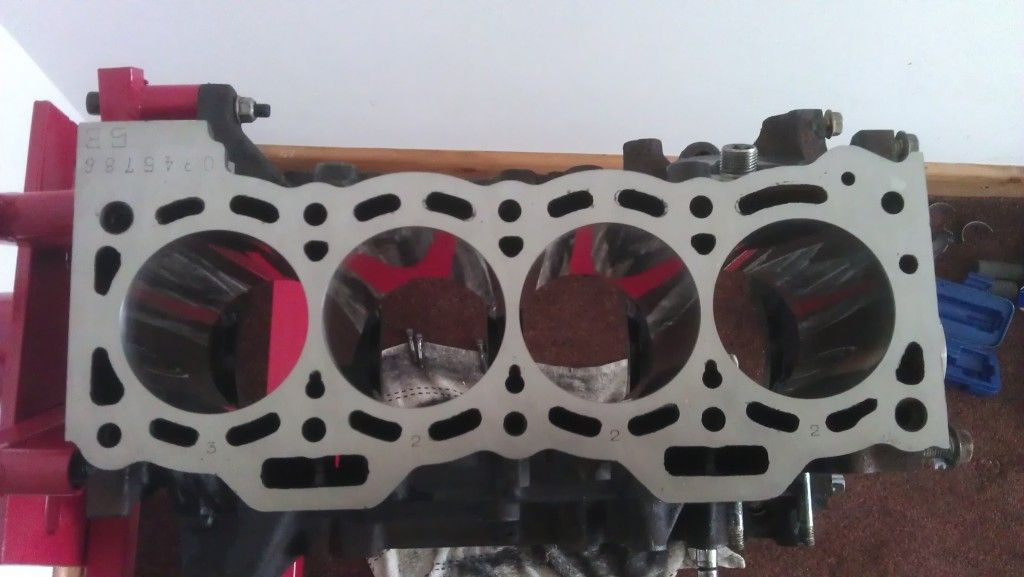
Da daddd, nice and smooth for the head gasket.
Now we will be getting the pistons and rods that the machine shop earlier put together for us, now in hindsight i wish i bloody did it my self, it takes 2 secconds to put the gudgeon pins in with the clips so save your self some money and do it your self
If you have got an electronic weighing scales, weigh the piston, rod and gudgeon pin all individually, you will notice that some parts are slightly heavier than others. You want it all balanced so try and get each piston/rod/bearing once assembled within say a 1 or 2 grams of each other.
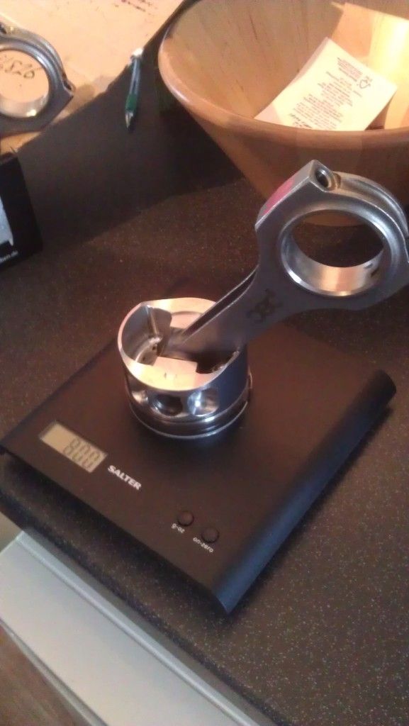
I weighed mine and got them within 1 gram of each other
Once thats done again fit the big end bearings to the notches and then apply the lube to the outside (dont cover the inside) they are notched like before so put them in like previous.
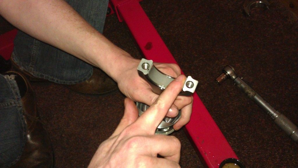
NOTE: Its really important you do not mix the caps up on the rods,this includes putting them back on the same rod in the opposite direction, they are machined to fit that rod and if you mix them then you can cock everything up. Number these with a pen to the corresponding piston so its impossible to mix them up before you start building it.
Gapping piston rings
This stage of the build is quite important and ensures we get a good seal on the bore for maximum compression, this needs to be done on any new pistons and ensures the rings get a good seal and allow adequate room for them to expand when they get hot.
Different rings have different specs so if your using standard rings use the 5e manual specs or if your using forged Wossner ones like me, use the spec sheet provided.
Here are the Wossner 74.5mm piston ring spec table.
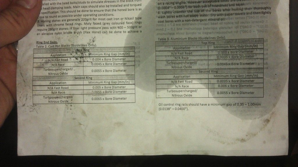
The top ring, the bottom ring and the oil rings have different gap requirements, so make sure you gap all of them.
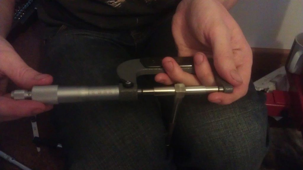
You need to measure each bore size with an internal micrometer or as i have done used telescopic measuring guages and then measured them with an accurate micrometer
get the width of the bore with the telescopic tube
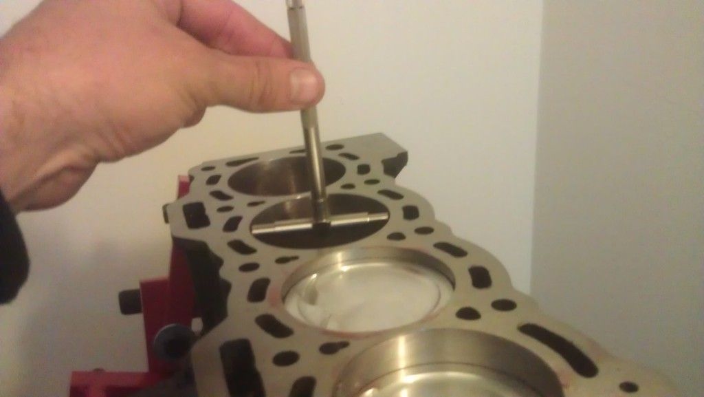
then measure it with a micrometer
once you have the bore width x it by the value in the box. Obviously its turbocharged so use that value
So for the 1st ring gap size (top) as an example my bore size is 74.5mm x 0.0055mm = 0.40975mm
2nd ring 74.5mm x 0.0065 = 0.48425mm
Oil rings can be between 0.35mm - 1.00mm
Now that we have these values we can fit the rings into that particular bore, remember you need to do this process for each bore as each bore may be slightly different in size.
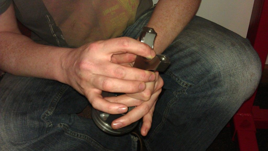
So get the piston ring, coat it in oil and press it in, use the piston to push it in and get it square as shown.
Once in you can see where the gap is, this is what we are going to measure. To measure it you will need some feeler guagues, they are only cheap about £5-10. Just make sure you get one that can go up in 0.01 0.02 and up increments as it has to be quite precise.
So the top ring gap has to be a minimum of 0.40975mm, get your feeler guague like above and put in say 0.4mm and then in an extra 0.01 and see if it fits, if it does, brilliant, if not you need to file down the gap until you get the desired size.
Read this on gapping rings, it will explain the best method on how to do it
http://www.circletra...1818/index.html
Then repeat the process for the rest of the rings on that piston, you need to repeat this process for the rest of the cylinders, remember to remeasure the bore and recalculate the figure for the correct gap size.
If its all a bit confusing feel free to drop me a line!
How to correctly fit your rings (clock them)
Your rings cant go on in any order so ensure you have the correct top, middle, and oil rings in place. The top two rings also need to go on in the correct way around, the Wossner ones have the writing on the top.

Where the gap is on the rings, you need to face this gap in the correct direction, each one needs to point a particular direction as shown in the diagram below.

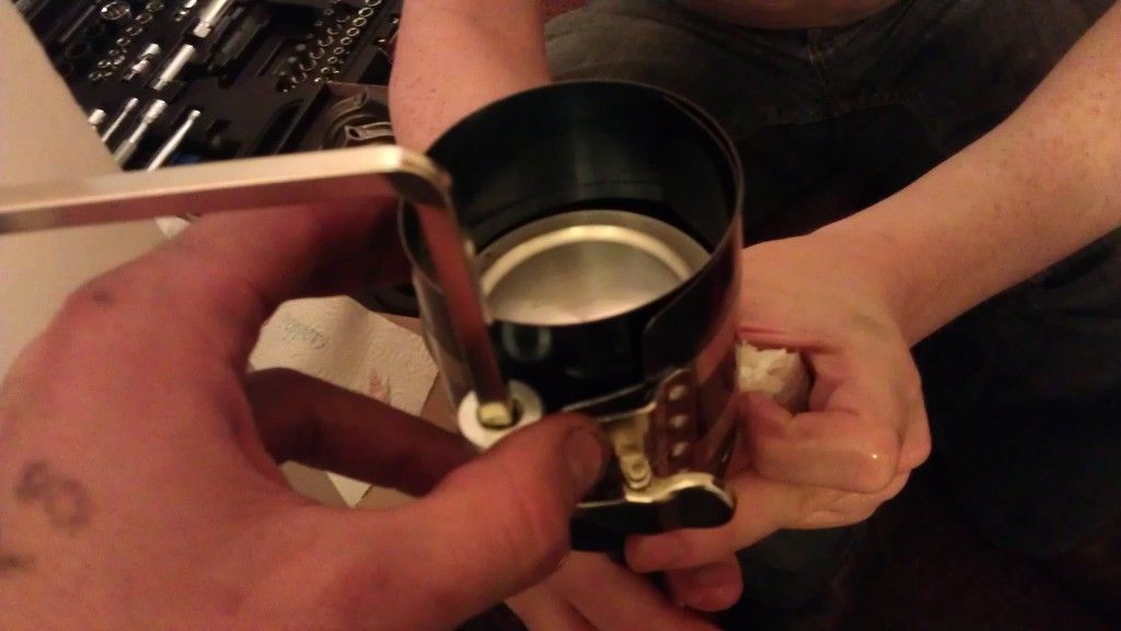
Now that the rings are gapped and pointing in the correct direction you are ready to put it into the bore. In order to get it to fit you need a piston ring compression tool, again about £11 from machine mart.
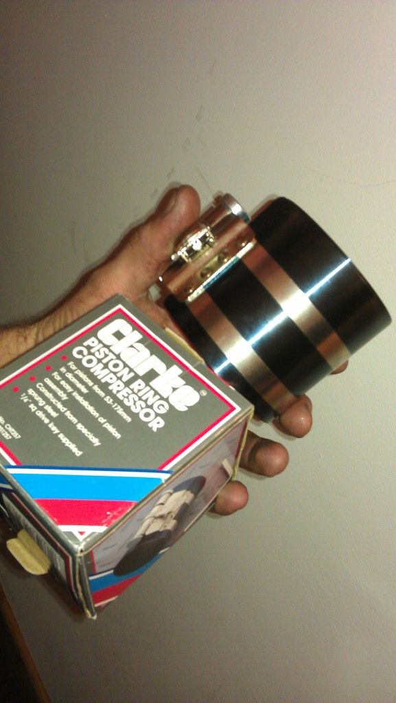
Its very easy to do you wrap the piston in it, tighten it and then place the piston into the bore. You can then tap it into position with a rubber mallet etc.
Note how the direction of the piston faces the intake side of the engine
Once you have fitted the first piston, you will need to line it up with the crank journal underneath and then put the matching cap on with your ARP bolts.
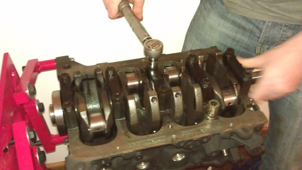
I missed the photos of the first piston being attached but here is a shot of me putting the 3rd one on,
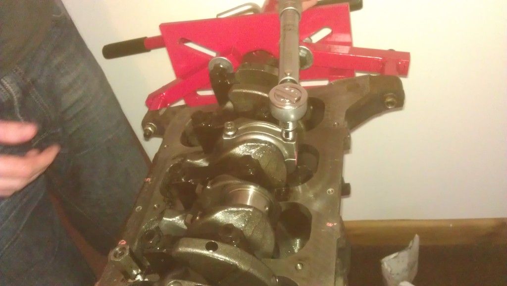
You can see that the cap is on ontop of the crank journal and i am tightening it up with a torque wrench. Make sure you put the main bearing on each side of the cap, coat it in oil and then tighten up. The big end ARP bolts need to be tightened down to a specefic torque, THIS IS VERY IMPORTANT.
The torque setting will be supplied with your rods, so again if your standard check the manaul or if your forged, use the spec sheet. Here is the Pec 5e Forged spec sheet.
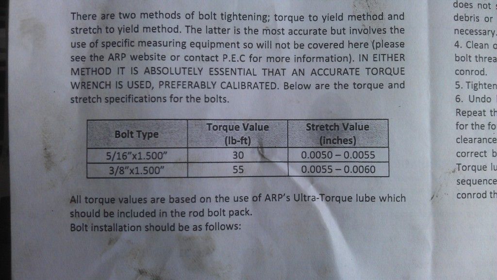
Its the top value that we are interested in, i converted it to Nm for my torque wrench so 40.7Nm, make sure you put on your ARP fastner lube and it will ensure you get the desired torque setting first time around.
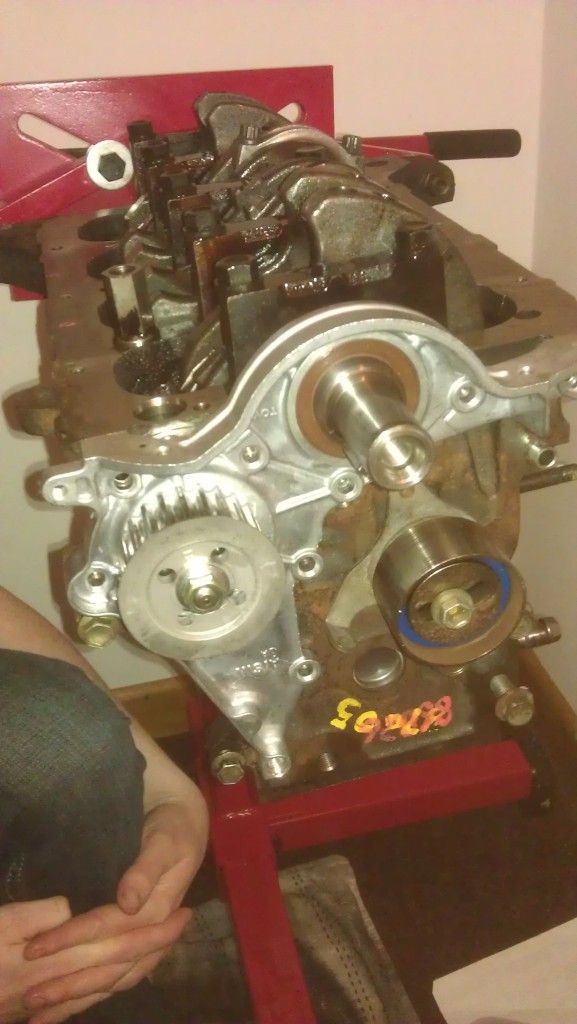
Once all the pistons are in and connected up well done, we can move on towards getting some of the other parts attached.
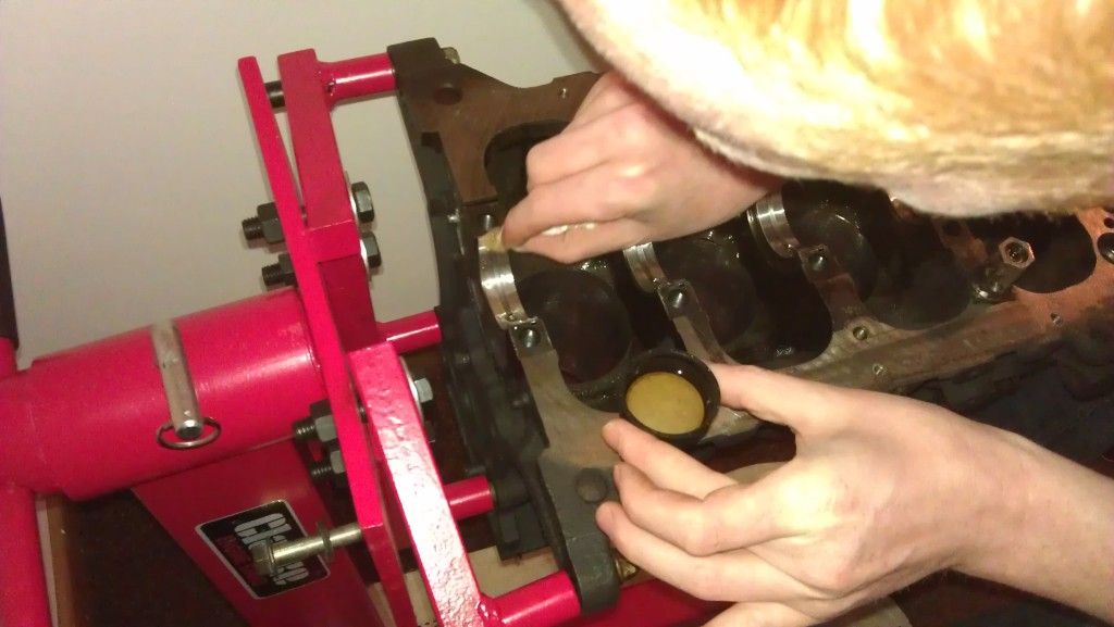
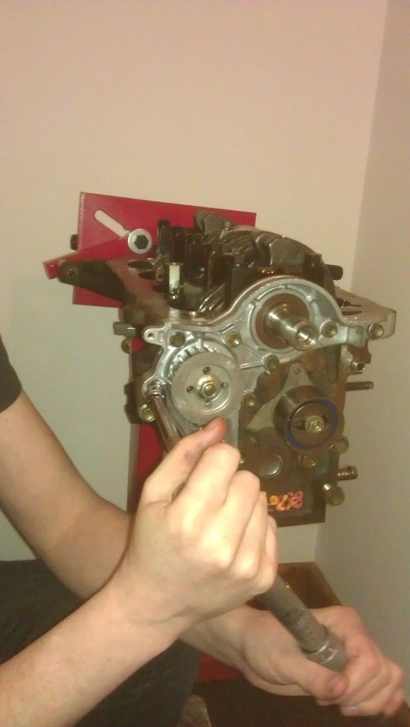
Oil pump fitment
Really important part of the engine, the oil pump! Always put a new one in if your doing a full rebuild, its not worth the risk of using an old one. Remember these engines are over 15 years old! Before we change it though we will change the rubber gasket which sits behind it, pry it out and put a nice new one in from your gasket set.
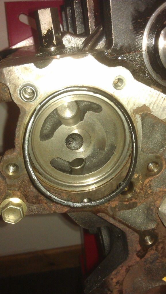
Once thats in you will need to press a new crank oll seal into your new oil pump, its that brown one in the picture already attached to the pump. Note this is a common failure point for oil leaks so make sure put a seam of oil on it to fit it and tap it in so its completly flush not ofset, make sure you dont ding it either!
If i remember correctly there are 10 bolts to fit it on, one has a little metal tag which is used to attach a spring to the cambelt tensioner. Tighten them all up ensuring the oil seal is snug on the crank.
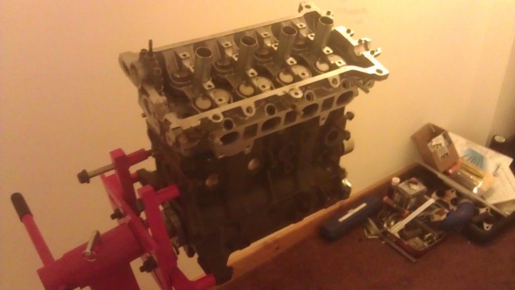
head gasket fitment
make sure both your head and block are clean and skimmed ready to accept the new gasket, i used an athena on mine.
fit the gasket on the dowles, then lower you head on in the correct direction as shown.
More to come this week
Note this is my build as of today 22/5/12, so its still being built. I welcome your comments and also if you think i have missed ANYTHING thats worth adding, please comment as i want it as accurate as i can for everyone
.
Index
Introduction
Parts required
Machine shop work
Tolerances on critical engine parts
Bottom end assembly
Introduction
So you consider your self a dummy but are keen to build engines and save your self some wonga, then read on. With this guide anyone should be able to build an engine who can follow my instuctions. Its not a black art and is actually fairly easy although it is quite time consuming getting all the measurements correct, in fact you spend more time measuring everything than you do building it! Although most of it is just knowing the correct procedure for everything
I am documenting this on my own forged 5E build
Now UKSC managed to loose my disasembly guide to go with this so this will currently just cover the reassembly, I'll rewrite it after i have put my engine back together! Note everything in here is for reference and I take no responsibility for anything in building your own engine and stuff going wrong, but follow this correctly and you will be fine.
TAKE NOTE!
So first rule of thumb in engine building, DO IT ONCE, DO IT RIGHT!!!!! Dont cut ANY corners and read this document about 10 times before you even start building it so you are familure with the build process. If you cut any of the steps out or rush building it, you may as well throw your money down the pan. Engine building is all about minute tollerances between parts and putting everything back together in a set sequence, thats the pep talk over, let go!!
Parts required for full rebuild
This is based on my 5e forged build, so if your building a standard or 4e obviously buy the respective corresponding parts. I will list the prices I paid also as of 28/3/12 So you can use for reference.
PEC forged 5e connecting rods - £400
74.5mm Wossner forged pistons - £450
Athena MLS 1.2mm headgasket - £100
Toyota full engine gasket set - £148
Toyota oil pump - £97.50
5E conversion flywheel (so you can use the larger 4e clutch) - £140
Water pump - £29.90
Timing belt - £25.50
Engine stand - £55.00
Piston ring compression tool (to fit pisons in the block) £11.98
ACL main bearings - £43
ACL big ends - £36
ACL thrustwashers -£12
Total: £1548.88
Obviously on top of this you need a 5e Donor engine which cost me £125 from a Toyota Paseo and you also need a 4E head and sump/strainer. In hindsight i drastically underated the build cost!!! so thats £1673.88 so far without any workshop costs!!!
Machine Shop work
Now that you have stripped the engine down to its bare parts i.e
Head
Block
Crank
Pistons and rods
We can begin to work on these parts to get them ready for assembly. First things first we need to take our block, head and crank down to the local engineering workshop who will inspect them to ensure they are useable (i.e not damaged) and that they are within tolerance, and if not they can be ground, polished etc.
In particular you need the following work done:
Get the head skimmed
Fit new head valve stem seals (you can do this your self if you have the tools)
Head chemically cleaned
Had the block bored oversize
Bores Cross hatched and honed
Block decked
Block Chemically cleaned
Block notched
Had the crank measured and polished
The Head
Before a chemical wash
After
Nice clean refreshed head with new valve stem seals
As part of the build you would have bought a full toyota engine gasket set, so when you give them the head ask them the change the valve stem seals for you (unless you have the tools to do it your self) and also check the head to ensure its straight. As a rule of thumb if your spending this much money on it, for the sake of £30 get it skimmed, even if your Head gasket hadnt failed. This way you know 100% the head is totally refurbed when you put it back together, DO IT ONCE DO IT RIGHT!!, It should also be chemically cleaned
So you want to ask for:
Valve stem seals changing (unless you can do it, need a special tool to remove valves)
Head skimmed
Chemically cleaned
possibly ported and polished if they do it.
The Block
The block will need to be cross hatched and honed to fit your standard size pistons, or if you are going oversize then bored out to the size of your pistons. 74.5mm is the common size for forged pistons, or a maximum of 75mm but this give no room for error if you damage the block in future, it will have to be scrapped.
Your new pistons will come with a spec sheet so give this to them. Also ensure you ask to get the block decked to ensure its straight and smooth to reveive the new HG (DONT LEAVE ANYTHING TO CHANCE!!). When you get it back give it a coat of high temp paint for the new look, just make sure you mask it all up
It should also be chemically cleaned.So you want:
Bored oversize if need be if your going oversize pistons
Honed and Cross hatched
Chemically cleaned
Top of the block decked
The Crank
The crank will either be standard size or it may have been skimmed in the past and be undersize, the workshop will check this for you and advise appropiate bearings. Always use ACL bearings for the main bearings, big ends and thrust washers. The crank journals should be free of scratches to be used and its advisable to get it polished, or ground if damaged.
If you dont have the tools to measure the journals your self, get the machine shop to do it, ask them to service the crank, measure it all up to toyota specs and also check for out of roundness.
Work required:
Polished or ground if unserivcable, you can go undersize 0.25 and 0.50
Pistons and rods
Give your pistons and rods to the machine shop and ask them to the attach the pistons to the rods, you will need to give them one of the standard ones so they can see what direction it attaches. I paid the workshop but in hindsight do it your self, i was under the impression you needed a press to do it but you can fit them without one as they just slide in, gutted! oh well
Once your pistons and rods are together you will also need to gap your piston rings acording to the spec sheet provided with your pistons and also you will need to "Clock" your rings so that they are put on in the correct direction. Again your spec sheet will provide you with this information.
Tolerances on critcal engine parts
Dependent on what your circumstances are on rebuilding your engine, you need to get a number of things checked to ensure that your engine parts are within tolerance of the specification as set out by Toyota. This is because parts could be worn out of shape or new parts may not be a 100% fit and so you need to check the specifications and get them spot on. DO NOT IGNORE THIS, IF YOU DO YOUR ENGINE WILL FAIL! In fact this is the most important part of engine building and is the main reason people doing this end up with a knackered engine.
I will post up the spec sheets shorly for the 5e which you need to follow to ensure your engine does not fail prematurely.
This is VITAL and includes
Measuring your existing bottom end bearings - they will either come in standard or oversize if the crank has been ground previously
Measuring your bores - This ensures that they are within specifcation and not worn out of shape past Toyotas recomendations
Measuring your piston ring gaps - Again even new new rings for any pistons need to be gapped,
Measure the crank for out of roundness - Ensure your crank is not worn unevenly which could cause premature bearing failure.
Measuring sideways crank drift - If your thrust washers are worn your crank may have to much sideways play
I'll be posting up more details and pictures of each of these processes this week.
You need accuarate tools to be able to measure most of the above, if you dont have these then you can do what I did and ask your machine shop to measure it all for you. It costs a bit more but its a must!!
Bottom end assembly
Parts Required:
ACL Main Bearings
ACL Big ends
ACL Thrust washers
Assembly lube
Torque Wrench
Micrometer, with telescopic tubes (measure your bores, bearings)
feeler guagues (Gap your piston rings)
So now you have spent a small fortune to get to this point its time to put it together, dont even think about doing this on a bench or the floor, go out and buy your self an engine stand. You can pick them up for about £50 and it will make things ten time easier as well as keep any dust contaminants away from the engine.
This is mine i bought it from machinemart new online for £55
NOTE: IT IS REALLY, REALLY important you build your engine in a clean environment, so your shed aint gonna cut it. One bit of crap in one of the journals, oil ways and the whole bottom end could fail. Build it in your house if your Mrs will let you lol, i went up my mates
Get your block and stick it onto your engine stand like this...
The first job is to fit the main bearings into the block journals, by this point you should have worked out what bearings you need be it standard or oversize.Measure them with a micrometer to find out or ask your workshop. So go get your ACL main bearings and pop them in like below, then line the notches up so then gently press them in to seat them properly. Make sure the journals are clean and free of any contaminants before you put each one in. Do not put any lube on the back of them or the seat.
Click all 5 in as shown below and then put a liberal coating of oil on all 5. "NOTE: DONT USE ENGINE OIL buy Engine Assembly lube" I found that the oil was to thin and after a couple of days it had all ran out the bottom, get some engine lube, its thick as hell and will ensure your engine doesnt scuff anything on initial start up.
Placing the final one in
Once you have put them all in it should look like this
Next is to fit the thrust washers in the centre on number 3 these stop the crank from floating sideways once its all tightened up, the are maked with lines on one side of them, these markings face OUTWARDS on both sides. Note: There are 4 of them, two for the bottom and two for the top, put the two in now coat them in lube so they stick, the other two go in later on.
The right one
The left one
Next is to get your polished crank and lube the main journals ready to lower it into the engine. Again coat the main journals in oil first onthe crank.
Lower it in really carefully and ensure its completly horizontal to snugly fit into the journals, you do not need to force it. Note: The crank has to face the correct direction as shown below, the crank pulley side goes the direction of the timing belt.
You can give the crank a little turn to ensure its seated properly, just keep an eye on those centre thrust washers as they might move, just make sure they are flush. If all is good it should turn freely with little resistance.
Next is to put the main caps on to hold the crank in place, these also need bearings put into them, there are 5 of of them and they are numbered 1-5, again cover the outside in oil once fitted.. It is very important you put these on the correct way and in the correct sequence. You will notice that each one has a number on the top and also a small peg in the middle to indicate the direction it should go. Number 1 starts on the clutch/flywheel side with the peg facing the timing belt and then 2,3,4,5 all follow the same pointing towards the timing belt side with those pegs.
Grab number 1 and put your bearing in (note the number on top)
Again like the other bearings, press them in with the notch facing the notch on the cap like above. Dont forget to coat it wil lube after you have put it in
Put all your caps on 1 through 5 (facing the correct way) not forgetting to put the last two thrust washers in number 3, again lube them to help them stick.
and then hand tighten all the crank bolts, make sure the caps sit nicely on top of its seating position ready to be tightened down.
The crank bolts need to be tightened with a torque wrench and need to be done in two stages of tightening. Also its important you put fastner on this bolts like below (follow the insructions for use)
REMINDER: ADD TORQUE SEQUENCE DIAGRAM
Once tightened increase the torque setting to 58Nm and again follow the above tightening sequence.
Next rotate the engine as the next stage is to fit your pistons and rods
So your engine should now be in this position
Looking down from the top we can see the crank below which is where our pistons are going to be attaching too
Note to those who noticed the block isnt decked, yes i sent it back, how much better is that!!!!
Da daddd, nice and smooth for the head gasket.
Now we will be getting the pistons and rods that the machine shop earlier put together for us, now in hindsight i wish i bloody did it my self, it takes 2 secconds to put the gudgeon pins in with the clips so save your self some money and do it your self
If you have got an electronic weighing scales, weigh the piston, rod and gudgeon pin all individually, you will notice that some parts are slightly heavier than others. You want it all balanced so try and get each piston/rod/bearing once assembled within say a 1 or 2 grams of each other.
I weighed mine and got them within 1 gram of each other
Once thats done again fit the big end bearings to the notches and then apply the lube to the outside (dont cover the inside) they are notched like before so put them in like previous.
NOTE: Its really important you do not mix the caps up on the rods,this includes putting them back on the same rod in the opposite direction, they are machined to fit that rod and if you mix them then you can cock everything up. Number these with a pen to the corresponding piston so its impossible to mix them up before you start building it.
Gapping piston rings
This stage of the build is quite important and ensures we get a good seal on the bore for maximum compression, this needs to be done on any new pistons and ensures the rings get a good seal and allow adequate room for them to expand when they get hot.
Different rings have different specs so if your using standard rings use the 5e manual specs or if your using forged Wossner ones like me, use the spec sheet provided.
Here are the Wossner 74.5mm piston ring spec table.
The top ring, the bottom ring and the oil rings have different gap requirements, so make sure you gap all of them.
You need to measure each bore size with an internal micrometer or as i have done used telescopic measuring guages and then measured them with an accurate micrometer
get the width of the bore with the telescopic tube
then measure it with a micrometer
once you have the bore width x it by the value in the box. Obviously its turbocharged so use that value
So for the 1st ring gap size (top) as an example my bore size is 74.5mm x 0.0055mm = 0.40975mm
2nd ring 74.5mm x 0.0065 = 0.48425mm
Oil rings can be between 0.35mm - 1.00mm
Now that we have these values we can fit the rings into that particular bore, remember you need to do this process for each bore as each bore may be slightly different in size.
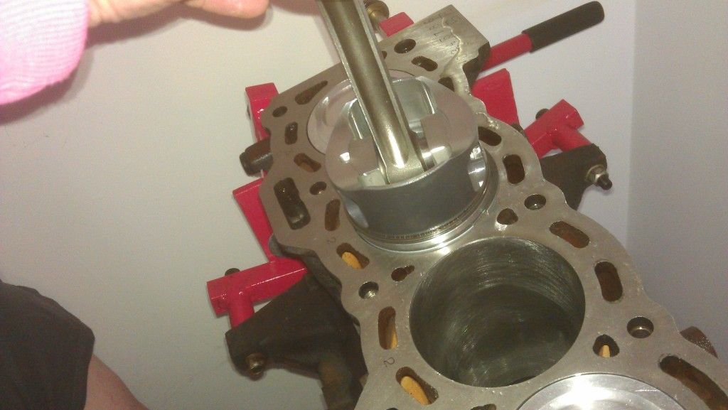
So get the piston ring, coat it in oil and press it in, use the piston to push it in and get it square as shown.
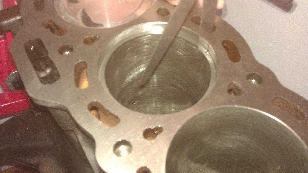
Once in you can see where the gap is, this is what we are going to measure. To measure it you will need some feeler guagues, they are only cheap about £5-10. Just make sure you get one that can go up in 0.01 0.02 and up increments as it has to be quite precise.
So the top ring gap has to be a minimum of 0.40975mm, get your feeler guague like above and put in say 0.4mm and then in an extra 0.01 and see if it fits, if it does, brilliant, if not you need to file down the gap until you get the desired size.
Read this on gapping rings, it will explain the best method on how to do it
http://www.circletra...1818/index.html
Then repeat the process for the rest of the rings on that piston, you need to repeat this process for the rest of the cylinders, remember to remeasure the bore and recalculate the figure for the correct gap size.
If its all a bit confusing feel free to drop me a line!
How to correctly fit your rings (clock them)
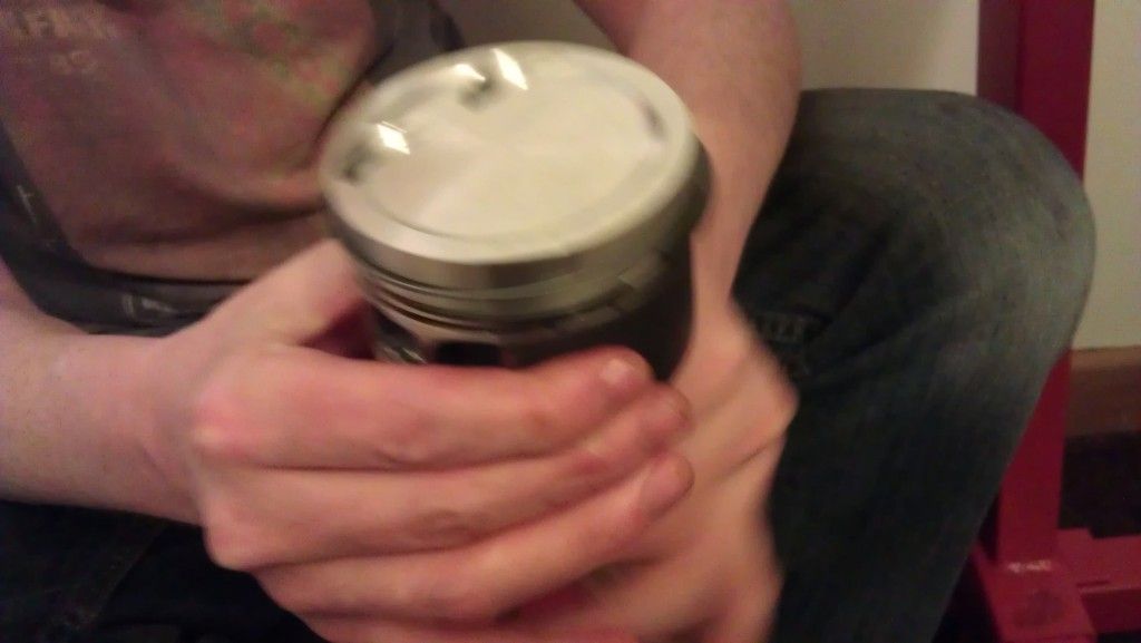
Your rings cant go on in any order so ensure you have the correct top, middle, and oil rings in place. The top two rings also need to go on in the correct way around, the Wossner ones have the writing on the top.
Where the gap is on the rings, you need to face this gap in the correct direction, each one needs to point a particular direction as shown in the diagram below.
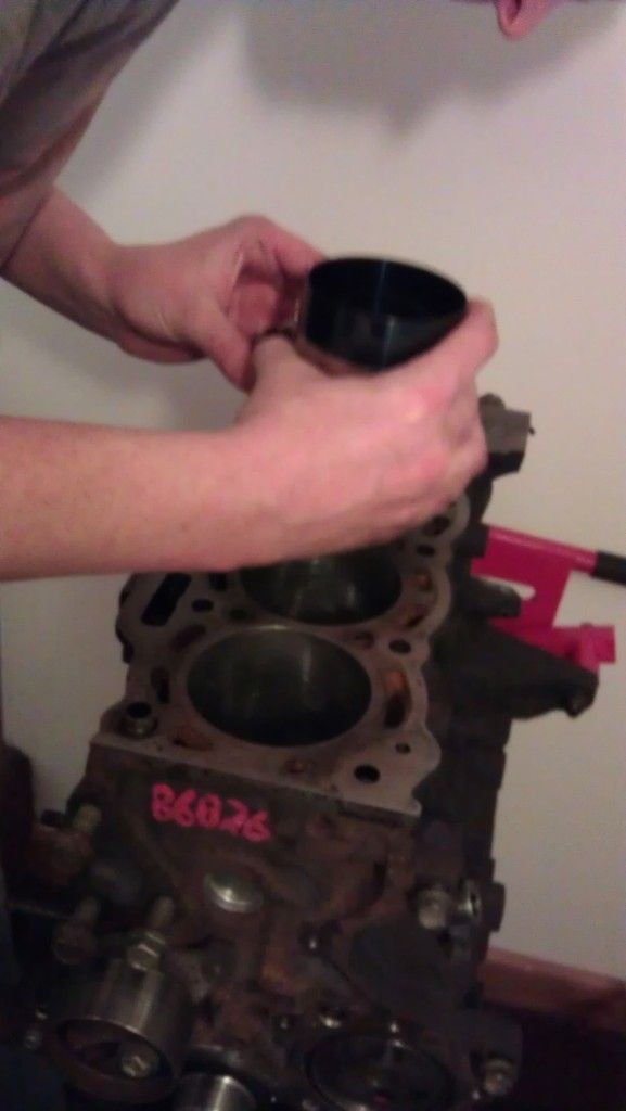
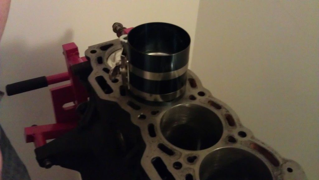
Now that the rings are gapped and pointing in the correct direction you are ready to put it into the bore. In order to get it to fit you need a piston ring compression tool, again about £11 from machine mart.
Its very easy to do you wrap the piston in it, tighten it and then place the piston into the bore. You can then tap it into position with a rubber mallet etc.
Note how the direction of the piston faces the intake side of the engine
Once you have fitted the first piston, you will need to line it up with the crank journal underneath and then put the matching cap on with your ARP bolts.
I missed the photos of the first piston being attached but here is a shot of me putting the 3rd one on,
You can see that the cap is on ontop of the crank journal and i am tightening it up with a torque wrench. Make sure you put the main bearing on each side of the cap, coat it in oil and then tighten up. The big end ARP bolts need to be tightened down to a specefic torque, THIS IS VERY IMPORTANT.
The torque setting will be supplied with your rods, so again if your standard check the manaul or if your forged, use the spec sheet. Here is the Pec 5e Forged spec sheet.
Its the top value that we are interested in, i converted it to Nm for my torque wrench so 40.7Nm, make sure you put on your ARP fastner lube and it will ensure you get the desired torque setting first time around.
Once all the pistons are in and connected up well done, we can move on towards getting some of the other parts attached.
Oil pump fitment
Really important part of the engine, the oil pump! Always put a new one in if your doing a full rebuild, its not worth the risk of using an old one. Remember these engines are over 15 years old! Before we change it though we will change the rubber gasket which sits behind it, pry it out and put a nice new one in from your gasket set.
Once thats in you will need to press a new crank oll seal into your new oil pump, its that brown one in the picture already attached to the pump. Note this is a common failure point for oil leaks so make sure put a seam of oil on it to fit it and tap it in so its completly flush not ofset, make sure you dont ding it either!
If i remember correctly there are 10 bolts to fit it on, one has a little metal tag which is used to attach a spring to the cambelt tensioner. Tighten them all up ensuring the oil seal is snug on the crank.
head gasket fitment
make sure both your head and block are clean and skimmed ready to accept the new gasket, i used an athena on mine.
fit the gasket on the dowles, then lower you head on in the correct direction as shown.
More to come this week
Last edited: