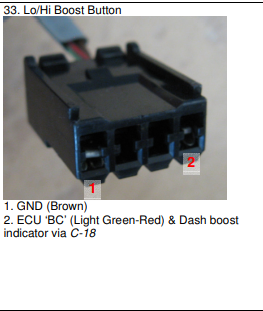
HI/LOW Boost wiring

Frankieflowers

Member +
Hi guys.

I am trying to figure out why my 4efte Glanza V Hi Low Boost solenoid isn’t working. The solenoid works, but the ECU isn’t putting the VSV1 signal to ground to engage the solenoid.
I am actually looking for the full manual in English because I have only a Russian version…
if you check the diagrams, you will see that VSV1 shares its signal with other ECU signals such as E+ (12V), DISC, FC (fuel cut), BATT and FB on the AC computer.
The purpose of my work was to put it back on its original setup so maybe someone could help me understand what is missing.
For instants as the engine is swapped into a E 11 Corolla the Starlet loom isn’t in besides the engine room that goes to the ECU. This explains why the engine oil pressure sensor isn’t connected to the loom. I want to know if this triggers the problem. about this missing connection I would like to know where the oil pressure wires go to reach the ECU.

I hope that someone can help. Thank you.
 

Frankieflowers

Member +
I was thinking about Hi Low boost the reason why the ECU doesn’t ground the solenoid. As we do not have a diagnostic to see the parameters. It might be that in the conditions where the whatever map sensor or temperature isn’t. In the nominal parameters, the ECU decides not to switch to.HI boost. I am just speculating, but I suppose that, as gaining boost in wrong conditions could create harm to the engine.
As the turbo installed on my engine is a hybrid ct9 with ct12 internals, the amount of pressure is approximately 20% higher compared to a stock ct9. This is why I think that’s probably the EC you doesn’t switch HI boost as the pressure is out of parameters. I must try changing the wastegate spring to a softer one to go back to nominal pressure behaviour even if the total pressure is the same (0.7 bar). The other thing to consider is that the solenoid on the Starlet works in a HI boost default position which means the solenoid is grounded and the air flows out. Then probably the internal actuator is set to 0.4 bat. I will do that test and if it won’t work, I will bypass the ECU and go straight from the switch ground to the solenoid. This was just an experiment for the pleasure to studying this amazing car. I don’t really need it to be in a stock set up as it is not a stock mechanical set up, and I am running a Piggyback with a map sensor clamp to avoid fuel cut. The test I have been done was of course, with a bypass
on the DET3.
 
Last edited:

zefinho10

Member +
If you find the enflish version id like to have a look too because im about to connect hi lo boost too!
By the waym do you remember what are the 2 cables' colours? Black and green ?
 

Frankieflowers

Member +
If you find the enflish version id like to have a look too because im about to connect hi lo boost too!
By the waym do you remember what are the 2 cables' colours? Black and green ?
Hello. After all the work, I have done to put the wiring back with the solenoid and the ECU as it was when it was stock it wasn’t working. The wiring was going out from the ECU to the solenoid properly and it was grounded on the engine properly, but it wasn’t working. On the activation side, which is the button on the Starlet the wiring was fine, but again it wouldn’t activate the solenoid. It’s a simple route, but the ECU decided not to activate it probably because I have a voltage clamp to avoid fuel cup with a piggyback. This is probably the reason why it wouldn’t work but all you need to do is to check the wiring on the solenoid side and find it if I remember well on pin 11. If it’s not pen 11 it’s been 21 Goes to the solenoid and the other two the switch.
When you find the wiring on the solenoid side, one of the two wires will have 12 V continues and the other one will be the ground when you put that ground on the chassis the solenoid opens, to let Air out. 0.5 bar when closed and 0.7 when open. It works fine and I tested it. I am running 1.1 bar on low boost and 1.3 on high boost.
The color of the wire that goes to the solenoid is of course black and the other color is if I remember well yellow. Definitely not red or something else but probably a light lime green.
 

zefinho10

Member +
Hey, did you figure out the colours of the hi lo cables?
1721277081054.png
It says its this bit i cant find it. The only one i have which is next to Δ button (alaram button) is one with black and green cables and its exactly the same with one, 4 pins and on 2 cables....
 

Frankieflowers

Member +
Wiring solenoid

VSV1 from ECU pin 11 (switch) ground signal
BC (Boost Control from ECU pin 20 (solenoid) ground signal

You need to go in the engine bay to find the 2 wires that come from the cabin. Test the signal between it and pin 20 on the first ecu loom connector.
One wire has a continuous 12V and the other is the ground.

the wires go from the steering pump to the fuse box area and get in the firewall.
Hey, did you figure out the colours of the hi lo cables?
View attachment 11498
It says its this bit i cant find it. The only one i have which is next to Δ button (alaram button) is one with black and green cables and its exactly the same with one, 4 pins and on 2 cables....
 

zefinho10

Member +
What colour are those 2 wires supposed to be?
Looks like i have to add those wires in my loom because there is not there. I dont have a GT dash loom but i bought one. But in the end looks like it is not from original GT... Hi lo is missing.
 

Frankieflowers

Member +
What colour are those 2 wires supposed to be?
Looks like i have to add those wires in my loom because there is not there. I dont have a GT dash loom but i bought one. But in the end looks like it is not from original GT... Hi lo is missing.
Sorry for the late reply. Now that you explained your situation, I can tell you the fastest way is to run two wires from the front of the engine all the way to the ECU. One will go to the 12 V continuous signal and the other one (ground) to a switch. It will be very simple to make the solenoid work.
 
Top