Mega squirt info

5e colin

Member +
There is no problem with the stock ignition man, thats what i am going to use.


bean reading different ?? the squirt cant run our external coil and dizzy ????

speadfreak is the only1 supposed off done this but not telling how !!!!!!!!!! he gives tips how to do the settings and a few wiring tips but when it comes to the actual wiring off the 2nd vr on the board ???????????

so its still a mistery !!!!

mayby chrisd knows ????
 

ChrisD

Member +
The 2nd var shouldn't have something to do with ignition. There shouldn't be a writing issue also. Not used a MS ecu, but you just need an ignition output from the ecu. This will go to the igt wire to the stock ignitor. The settings in the ecu should be distributor, constant charge (dumb type), around 3.5ms dwell time.
 

5e colin

Member +
hey j that page i did not read before ( 2 ) nice 1 but does it still need a crankshaft senser signal ???? bit confusing , is the 2nd vr for dizzy or crank ??? like edis signal etc etc
 

triple j

Member +
Yes Colin 1 sensor picks up the 24 tooth and the other picks up the 1 ( single pulse per revolution) which will calculate tdc.
 

ChrisD

Member +
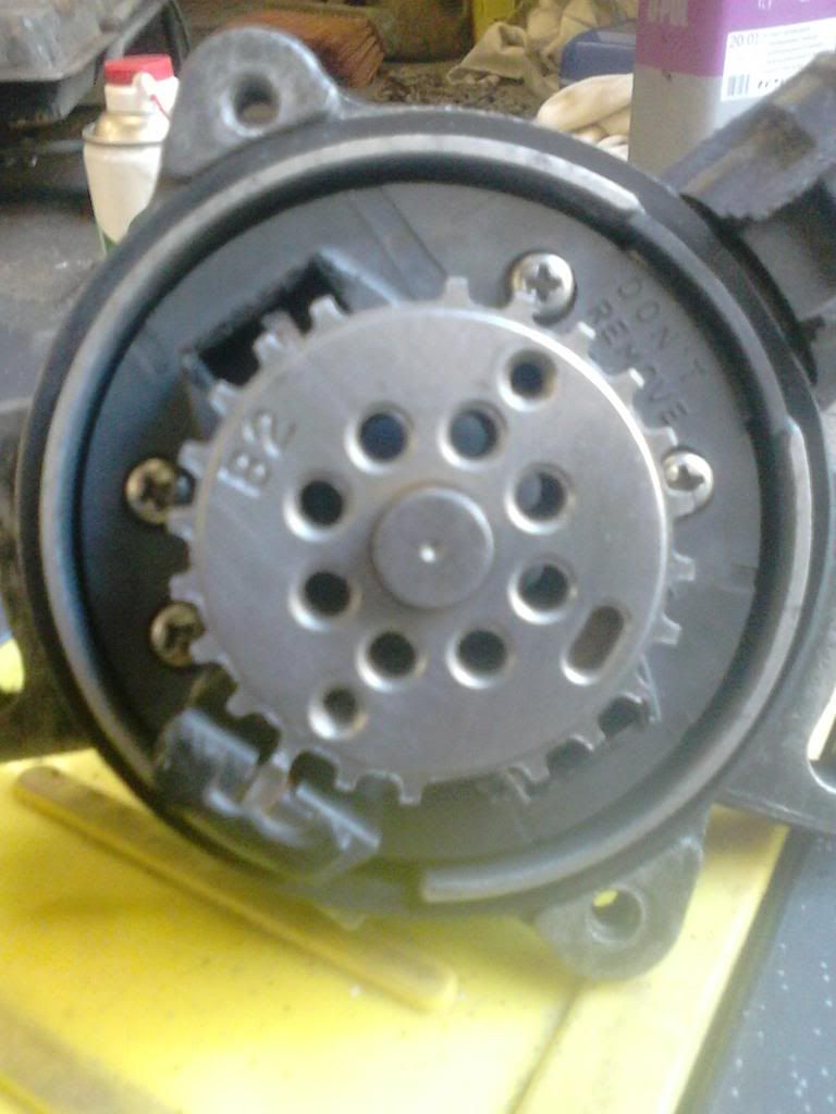
You neeed the 2nd VR for sure, as above Ne signal (24 tooth) is the rpm, while G1 or G2 (the single tooth) sets the correlation between TDC and the 24 tooth wheel.

For example:

Lets say you name each of the 24 tooth with 1, 2, 3, ..., 24. Let say the single tooth is between 2nd and 3rd teeth. The ecu reads it and will count a number of teeth on the 24 wheel and start the injection/ignition cycle again. This number actually shows the TDC in relation to the NE wheel.
 

ChrisD

Member +
I actually never disagreed... My comment on the 2nd VR was for the above quoted post.

bean reading different ?? the squirt cant run our external coil and dizzy ????

speadfreak is the only1 supposed off done this but not telling how !!!!!!!!!! he gives tips how to do the settings and a few wiring tips but when it comes to the actual wiring off the 2nd vr on the board ???????????

so its still a mistery !!!!

mayby chrisd knows ????
 

triple j

Member +
I will Colin am dedicated at this stage, this is s good thread am going to keep it up to date with how am getting on.
 

triple j

Member +
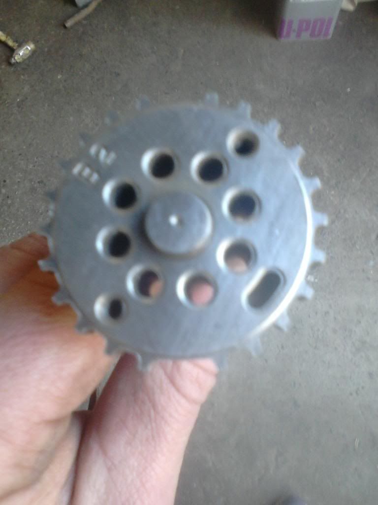
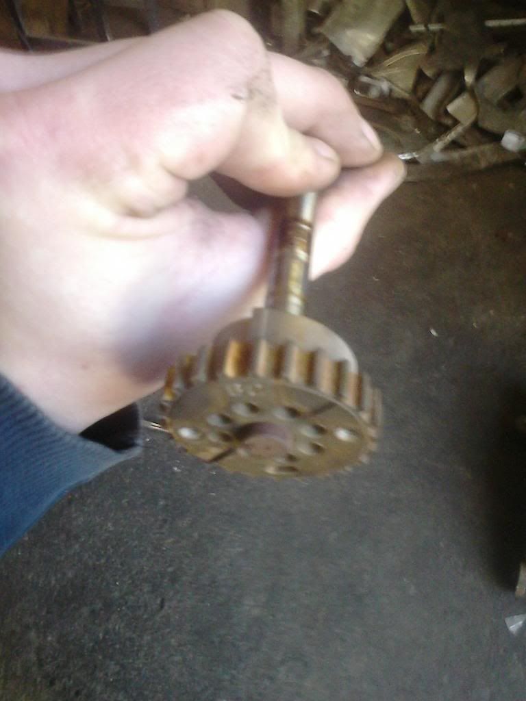
Will do solojdm, i have the ecu working with the stimulator and software, am going to go without the 2nd vr circut now as there is another way, the dizzy needs a little mod by grinding out 2 teeth of the 24 toothed wheel so its then a 12-1 wheel, http://www.performanceprobe.com/forum/showthread.php?t=30888 this guy shows how the mod is done on down the page, our dizzy is the very same only our 24 toothed wheel is on top of the single one, i have a spare dizzy here so i will give it a go.
 

triple j

Member +
Dizzy mod done, count across 4 teeth to the right from the lower 1 toothed wheel, this is your first missing tooth and the next is 180degrees across.
DSC_0059_zpsqjragqzj.jpg

File them out tidy, i used a small square file and finished them down with emery tape.
DSC_0062_zpsccetaq7j.jpg

Put back together, i removed the magnets from the top of the 2 unused sensors.
DSC_0065_zpsbn3nqrz9.jpg
 

ChrisD

Member +
You could just use the stock 24-1setup...but this motronic like setup will work fine for wasted spark and batch injection
 

triple j

Member +
From what a gather for setup, the car should be set tdc on cylinder 1 then the dizzy set 4 teeth before gap something like that, ms base timing set to 10 btdc, am not fully sure but am sure there will be some fiddling and timing light checking.
 

triple j

Member +
No Colin this is for 1 vr circuit, the dizzy turns at half the speed of the crank so each missing tooth on the dizzy is tdc.
 
Top