MARK@CMBAUTOS
Trader
As Ted says, they have to be spot on, or they wont work.
x2
As Ted says, they have to be spot on, or they wont work.
Sorry, I missed that bit mate. How did you go about timing up each cam? Did you just attempt to align them by eye, or did you use a dial gauge and timing disc to make a TDC mark for each camshaft?
I get what your saying about the cam gears limiting the amount of available adjustment, I'm just trying to understand how you've confirmed it's not possible (I'm not saying it is possible) to align the cams into a position where they produce a usable result.
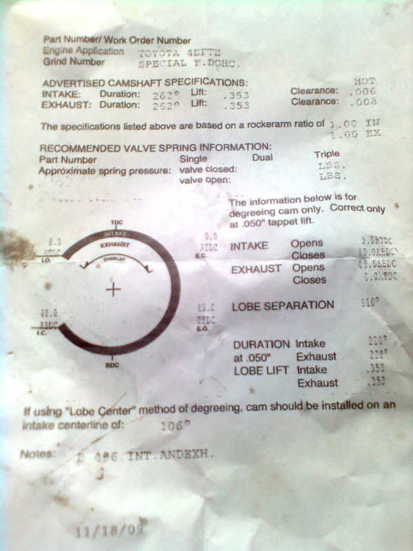
Sam throw up a copy of the data sheet for the cams. Let everybody see.
")
As below Sam.
If i cant see a data sheet before the end of the week from Sam, then these will be getting thrown in the feild at the house, even still cut up into 16 lobes for key rings, hell Sam ill even send you one.
Waste of £350 but ill never buy any Speedvision products again.
If yes just ignore the top marks put 1st cylinder at tdc and put both cams in such a way that both have their valves open at full lift.(idealy you need the exhaust valve to have more lift than intake) With this way you will be as close as possible.
Chris
so ur saying that most of the cams u do dont line up and this is what you do to make them work?
Rwading this again, how would that work?
Even on exhaust stroke (piston on the way up near TDC), exhaust valve should be near closed and inlet just opening (depending on cam timing and overlap) - if both were full open your piston would just have exhausted all your charge straight up the inlet. You would keep the zorst valve open a wee bit because you get a "suction" effect from the outrushing gas that pulls more inlet charge in.
Whats your thoughts?
Rory
and i will make them RUN.Rory it is the overlap i mean. At tdc you need both valve open with the exhaust valve a litle bit more lift than intake. You need to have a bit more lift to exhaust cause when you put the belt back in will throw it a bit on one side.
To get it right if you move the crank the direction it normally rotates will close the exhaust and gradually open the intake. Thats why you need to data sheet to figure out at wich deggree of the crank you should have how much lift and at wich degrre you need each valve close or open.
Adjusting with the way i tell you it will not be grand but you will not have running issues. Will be less than a teeth out of what it should be.
Ofcource then you need to readjust the pin so the gears shit in the right degrees.
Finaly if you dont want them you can throw them to my address...
The other way you can do it is to put the standard cams back on and mesure them. At wich degrees they have full lift. Then you put new cams in and adjust like it was oem. Dont know if you get it.
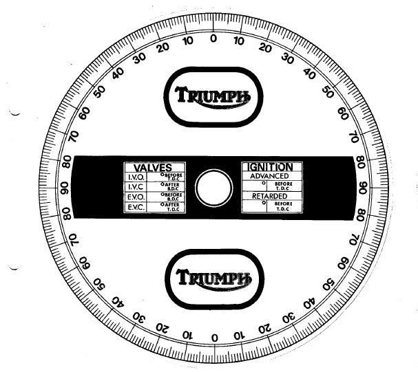
You need an angle disc paper for the crank tho..and a depth caliper attached to the valve shim.
Chris
did everyone that bought these cams get a data sheet? because i never
Nor did i, my head was f*ck'd hard with these cams. Due to this i lost alot of moneydid everyone that bought these cams get a data sheet? because i never
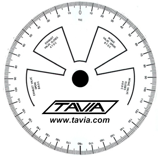
sorted now lads get them timed up ps ted i have a timing disc if u need one